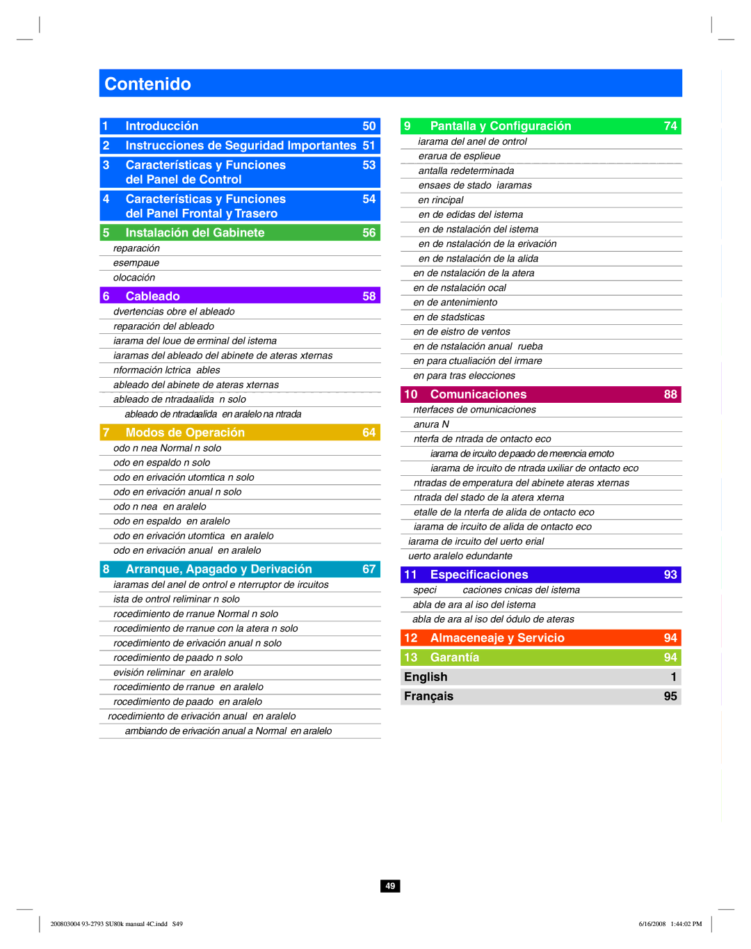
Contenido

1

1 Introducción

50


9 Pantalla y Configuración

74

2

Instrucciones de Seguridad Importantes 51


3

Características y Funciones

53


del Panel de Control


4

Características y Funciones

54


del Panel Frontal y Trasero


5

Instalación del Gabinete

56

5-1

Preparación

56


5-2

Desempaque

56


5-3

Colocación

57


6

Cableado

58

6-1

Advertencias Sobre el Cableado

58


6-2

Preparación del Cableado

58


6-3

Diagrama del Bloque de Terminal del Sistema UPS

59


6-4

Diagramas del Cableado del Gabinete de Baterías Externas

59


6-5

Información Eléctrica y Cables

60


6-6

Cableado del Gabinete de Baterías Externas

61


6-7

Cableado de Entrada/Salida CA (Un solo UPS)

62


6-8

Cableado de Entrada/Salida CA (UPS en Paralelo –Una Entrada)

63


7

Modos de Operación

64

7-1

Modo En Línea (Normal) (Un solo UPS)

64


7-2

Modo en Respaldo (Un solo UPS)

64


7-3

Modo en Derivación Automática (Un solo UPS)

64


7-4

Modo en Derivación Manual (Un solo UPS)

64


7-5

Modo En Línea (UPS en Paralelo)

65


7-6

Modo en Respaldo (UPS en Paralelo)

65


7-7

Modo en Derivación Automática (UPS en Paralelo)

65


7-8

Modo en Derivación Manual (UPS en Paralelo)

66


8

Arranque, Apagado y Derivación

67

8-1

Diagramas del Panel de Control e Interruptor de Circuitos

67


8-2

Lista de Control Preliminar (Un solo UPS)

67


8-3

Procedimiento de Arranque Normal (Un solo UPS)

67


8-4

Procedimiento de Arranque con la Batería (Un solo UPS)

68


8-5

Procedimiento de Derivación Manual (Un solo UPS)

69


8-6

Procedimiento de Apagado (Un solo UPS)

69


8-7

Revisión Preliminar (UPS en Paralelo)

70


8-8

Procedimiento de Arranque (UPS en Paralelo)

70


8-9

Procedimiento de Apagado (UPS en Paralelo)

71


8-10

Procedimiento de Derivación Manual (UPS en Paralelo)

72


8-11

Cambiando de Derivación Manual a Normal (UPS en Paralelo) 73


9-1

Diagrama del Panel de Control

74


2

9-2

Jerarquía de Despliegue

74


9-3

Pantalla Predeterminada

75


9-4

Mensajes de Estado y Diagramas

75


9-5

Menú Principal

77


3


9-6

Menú de Medidas del Sistema UPS

77


9-7

Menú de Instalación del Sistema UPS

78


9-8

Menú de Instalación de la Derivación

78


9-9

Menú de Instalación de la Salida

79


4


9-10

Menú de Instalación de la Batería

80


9-11

Menú de Instalación Local

82


9-12

Menú de Mantenimiento

83


9-13

Menú de Estadísticas

84


5


9-14

Menú de Registro de Eventos

85


9-15

Menú de Instalación Manual y Prueba

86


9-16

Menú para Actualización del Firmware

87


9-17

Menú para Otras Selecciones

87


6


10

Comunicaciones

88


10-1

Interfaces de Comunicaciones

88


10-2

Ranura SNMPWEBCARD

88


10-3

Interfaz de Entrada de Contacto Seco

88


7


10-4

Diagrama de Circuito de Apagado de Emergencia Remoto (EPO) 89


10-5

Diagrama de Circuito de Entrada Auxiliar de Contacto Seco

89


10-6

Entradas de Temperatura del Gabinete Baterías Externas

89


10-7

Entrada del Estado de la Batería Externa

89


8


10-8

Detalle de la Interfaz de Salida de Contacto Seco

90


10-9

Diagrama de Circuito de Salida de Contacto Seco

91


10-10

Diagrama de Circuito del Puerto Serial RS-232

92


10-11

Puerto Paralelo Redundante

92


9

11

Especificaciones

93


11-1

Especificaciones Técnicas del Sistema UPS

93


11-2

Tabla de Carga al Piso del Sistema UPS

93


10

11-3

Tabla de Carga al Piso del Módulo de Baterías

93


12

Almaceneaje y Servicio

94


13

Garantía

94


English

1


11


Français

95


12


13


49

200803004 93-2793 SU80k manual 4C.indd S49

6/16/2008 1:44:02 PM

Page 49
Image 49
Tripp Lite SU80K owner manual Contenido, English Français

SU80K specifications

The Tripp Lite SU80K is a robust and reliable uninterruptible power supply (UPS) solution, designed to provide essential backup power to critical equipment in various environments such as data centers, telecommunications, and industrial settings. This high-capacity UPS offers 80 kVA of power, ensuring optimal protection for vital systems against power interruptions and fluctuations.

One of the main features of the SU80K is its advanced double-conversion technology, which provides clean and consistent power by converting incoming AC power to DC and then back to AC. This process not only isolates connected equipment from raw utility power, but it also ensures that sensitive electronic devices maintain a steady voltage and frequency, ultimately enhancing their performance and lifespan.

In terms of efficiency, the SU80K is equipped with an energy-efficient design that maximizes operation while minimizing energy consumption. The unit operates with an efficiency rating of up to 97% in online mode, which contributes to reduced operational costs over time and is especially beneficial for large-scale deployments.

Another notable characteristic of the SU80K is its modular design, which allows for flexibility and scalability. Users can add additional battery packs to extend runtime, enabling the UPS to adapt to changing power needs without requiring complete system replacement. This feature is particularly advantageous for growing businesses that need to expand their backup power capabilities progressively.

The SU80K also includes advanced monitoring and management options, with an optional network management card that enables remote monitoring via a web interface. This capability provides real-time data on the UPS’s status, battery health, and load levels, allowing IT administrators to make informed decisions to maintain system availability.

Additionally, the UPS features multiple communication ports, including RS-232 and USB interfaces, ensuring compatibility with various devices and ease of integration into existing systems. It also supports SNMP protocols, allowing for seamless integration with network management systems.

Overall, the Tripp Lite SU80K combines high performance, advanced features, and user-friendly management options to create an ideal solution for businesses that require reliable and efficient power protection for their critical equipment. With its strong build quality and commitment to performance, the SU80K stands out as a versatile choice for ensuring business continuity in the face of power disturbances.