 Set-up
Connecting with a host computer
This section describes the settings for connection with a host computer.
CAUTION
![]() Make sure that the power switch is switched to OFF when connecting with a host computer or making settings.
Make sure that the power switch is switched to OFF when connecting with a host computer or making settings.
1. Set the BUS switches.
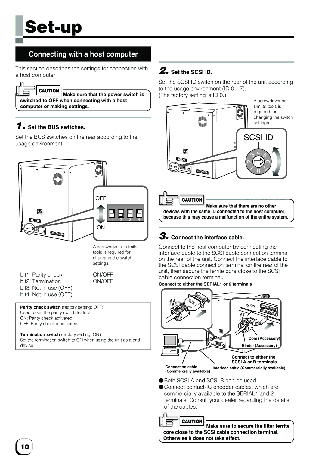
Set the BUS switches on the rear according to the usage environment.
| OFF |
|
|
|
| 1 | 2 | 3 | 4 |
| ON |
|
|
|
| A screwdriver or similar | |||
| tools is required for |
| ||
| changing the switch |
| ||
| settings. |
|
|
|
bit1: Parity check | ON/OFF |
|
|
|
bit2: Termination | ON/OFF |
|
|
|
bit3: Not in use (OFF) |
|
|
|
|
bit4: Not in use (OFF) |
|
|
|
|
Parity check switch (factory setting: OFF)
Used to set the parity switch feature.
ON: Parity check activated
OFF: Parity check inactivated
Termination switch (factory setting: ON)
Set the termination switch to ON when using the unit as a end device.
2. Set the SCSI ID.
Set the SCSI ID switch on the rear of the unit according to the usage environment (ID 0 – 7).
(The factory setting is ID 0.)
A screwdriver or similar tools is required for changing the switch settings.
SCSI ID
3 | 4 | 5 |
| ||
|
| |
2 |
| 6 |
1 | 0 | 7 |
|
|
CAUTION
![]() Make sure that there are no other devices with the same ID connected to the host computer, because this may cause a malfunction of the entire system.
Make sure that there are no other devices with the same ID connected to the host computer, because this may cause a malfunction of the entire system.
3. Connect the interface cable.
Connect to the host computer by connecting the interface cable to the SCSI cable connection terminal on the rear of the unit. Connect the interface cable to the SCSI cable connection terminal on the rear of the unit, then secure the ferrite core close to the SCSI cable connection terminal.
Connect to either the SERIAL1 or 2 terminals
| Core (Accessory) |
| Binder (Accessory) |
| Connect to either the |
| SCSI A or B terminals |
Connection cable | Interface cable (Commercially available) |
(Commercially available) |
|
⬤Both SCSI A and SCSI B can be used.
⬤Connect
CAUTION
![]() Make sure to secure the filter ferrite core close to the SCSI cable connection terminal. Otherwise it does not take effect.
Make sure to secure the filter ferrite core close to the SCSI cable connection terminal. Otherwise it does not take effect.
10
