PLS-345 - Physical Layer Switch; User's Guide
Physical Layer Switch v1.00 | Site | ID: |
| |
Display |
|
|
|
|
/H | Display Help Screen |
|
|
|
/S | Display Circuit Status |
|
|
|
/SN | Display Network Status |
|
|
|
Configuration |
|
|
| |
/G | View/Set General Parameters |
|
| |
/P [n] | View/Set Circuit Parameters |
|
| |
/N | View/Set Network Parameters |
|
| |
/M | View/Set Monitor Parameters |
|
| |
/DL | Download Configuration to File |
|
| |
Control |
| + | ||
/A <n> | Switch Circuit n to A | [n] | = optional ckt. common name or number | |
/B <n> | Switch Circuit n to B | <n> | = required ckt. common name or number | |
/D | Set Circuits to Default | n+n | or n n = ckt. n and ckt. n | |
/T | Reset Network Interface | n:n | = ckt. n through ckt. n | |
/X | Exit/Disconnect | * | = all ckts. | |
|
| ,y | = bypass "Sure? (y/n)" | |
|
| + | ||
PLS>
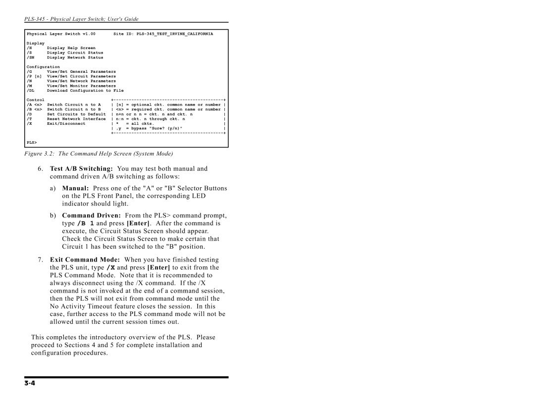
Figure 3.2: The Command Help Screen (System Mode)
6.Test A/B Switching: You may test both manual and command driven A/B switching as follows:
a)Manual: Press one of the "A" or "B" Selector Buttons on the PLS Front Panel, the corresponding LED indicator should light.
b)Command Driven: From the PLS> command prompt, type /B 1 and press [Enter]. After the command is execute, the Circuit Status Screen should appear. Check the Circuit Status Screen to make certain that Circuit 1 has been switched to the "B" position.
7.Exit Command Mode: When you have finished testing the PLS unit, type /X and press [Enter] to exit from the PLS Command Mode. Note that it is recommended to always disconnect using the /X command. If the /X command is not invoked at the end of a command session, then the PLS will not exit from command mode until the No Activity Timeout feature closes the session. In this case, further access to the PLS command mode will not be allowed until the current session times out.
This completes the introductory overview of the PLS. Please proceed to Sections 4 and 5 for complete installation and configuration procedures.
