OPERATION
ENERGY MANAGEMENT MODE
UTILITY GRID |
| AC |
|
IN BRIEF
INVERTER/ CHARGER
DC
BATTERY
AC |
| AC LOADS |
|
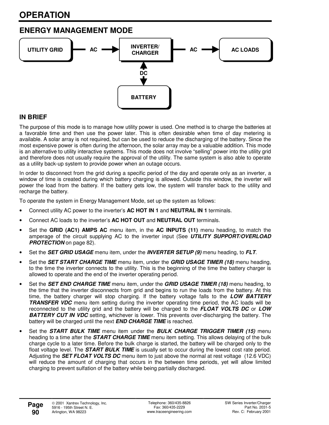
The purpose of this mode is to manage how utility power is used. One method is to charge the batteries at a favorable time and then use the power later. This is often desirable when time of day metering is available. A solar array is not required, but can be used to reduce the discharging of the battery. Since the most expensive power is often during the afternoon, the solar array may be a valuable addition. This mode is an alternative to utility interactive systems. This mode does not involve “selling” power into the utility grid and therefore does not usually require the approval of the utility. The same system is also able to operate as a utility
In order to disconnect from the grid during a specific period of the day and operate only as an inverter, a window of time is created during which battery charging is allowed. Outside this window, the inverter will power the load from the battery. If the battery gets low, the system will transfer back to the utility and recharge the battery.
To operate the system in Energy Management Mode, set up the system as follows:
•Connect utility AC power to the inverter’s AC HOT IN 1 and NEUTRAL IN 1 terminals.
•Connect AC loads to the inverter’s AC HOT OUT and NEUTRAL OUT terminals.
•Set the GRID (AC1) AMPS AC menu item, in the AC INPUTS (11) menu heading, to match the amperage of the circuit supplying AC to the inverter input (See UTILITY SUPPORT/OVERLOAD PROTECTION on page 82).
•Set the SET GRID USAGE menu item, under the INVERTER SETUP (9) menu heading, to FLT.
•Set the SET START CHARGE TIME menu item, under the GRID USAGE TIMER (18) menu heading, to the time the inverter connects to the utility. This is the beginning of the time the battery charger is allowed to operate and the end of the inverter operating period.
•Set the SET END CHARGE TIME menu item, under the GRID USAGE TIMER (18) menu heading, to the time that the inverter disconnects from grid and begins to run the loads from the battery. At this time, the battery charger will stop charging. If the battery voltage falls to the LOW BATTERY TRANSFER VDC menu item setting during the inverter operating time period, the AC loads will be reconnected to the utility grid and the battery will be charged to the FLOAT VOLTS DC or LOW BATTERY CUT IN VDC setting, whichever is lower. This prevents
•Set the START BULK TIME menu item under the BULK CHARGE TRIGGER TIMER (15) menu heading to a time after the START CHARGE TIME menu item setting. This allows delaying of the bulk charge cycle to a later time. Before the bulk charge is started, the battery will be charged only to the float voltage level. The START BULK TIME is usually set to occur during the lowest cost rate period. Adjusting the SET FLOAT VOLTS DC menu item to just above the normal at rest voltage (12.6 VDC) will reduce the amount of charging that occurs in the between time periods, yet will allow limited charging to prevent sulfation of the battery while being partially discharged.
Page
90
2001 Xantrex Technology, Inc. | Telephone: | SW Series Inverter/Charger |
5916 - 195th Street N. E. | Fax: | Part No. |
Arlington, WA 98223 | www.traceengineering.com | Rev. C: February 2001 |
