Owner’s Manual
With Revision 4.01 Software
SW Series Inverter/Chargers
2001 Xantrex Technology, Inc
5916 - 195th Street N. E
2001 Xantrex Technology, Inc
Telephone 360/435-8826
Arlington, WA
PRODUCT MATERIALS PACKAGE
5916 - 195th Street N. E
2001 Xantrex Technology, Inc
Telephone 360/435-8826
Arlington, WA
IMPORTANT SAFETY INSTRUCTIONS
TABLE OF CONTENTS
TABLE OF CONTENTS
CONTROLS, INDICATORS AND COMPONENTS
APPENDIX
TABLE OF CONTENTS
WARRANTY/REPAIR INFORMATION
INDEX
Figure 1, Identification Label
INDEX OF FIGURES
TABLE OF CONTENTS
Table 1, AC Input and Output Wiring Connections
INDEX OF TABLES
TABLE OF CONTENTS
Safety
IMPORTANT SAFETY INSTRUCTIONS IMPORTANT SAFETY INSTRUCTIONS
GENERAL PRECAUTIONS
SAVE THESE INSTRUCTIONS
WARNING - RISK OF EXPLOSIVE GASSES
IMPORTANT SAFETY INSTRUCTIONS
SPECIAL NOTICES
Page
Page
PERSONAL PRECAUTIONS
IMPORTANT SAFETY INSTRUCTIONS
2001 Xantrex Technology, Inc
IMPORTANT SAFETY INSTRUCTIONS
Page
Telephone 360/435-8826
INTRODUCTION INTRODUCTION
Page
2001 Xantrex Technology, Inc
INTRODUCTION
Page
Telephone 360/435-8826
Page
UNIT IDENTIFICATION UNIT IDENTIFICATION
MODEL NUMBER
Figure 1, Identification Label
2001 Xantrex Technology, Inc
UNIT IDENTIFICATION
Page
Telephone 360/435-8826
DISPLAY
CONTROLS, INDICATORS AND COMPONENTS
CONTROL PANEL
Figure 2, SW Series Inverter/Charger
MENU ACCESS/ADJUSTMENT BUTTONS Black
RESET TO FACTORY DEFAULTS BUTTON
LED STATUS INDICATORS
CONTRAST CONTROL
AC2 IN GOOD Green
ERROR Red
AC1 IN GOOD Green
BULK Yellow
STACKING PORT
AC SIDE
REMOTE PORT
INVERTER/CHARGER CIRCUIT BREAKER
LED INDICATORS
INTERNAL COMPONENTS AND INDICATORS
Figure 5, Internal Components and Indicators
RY7 Yellow LED
AUXILIARY AND GENERATOR CONTROL RELAY CONNECTORS
BATTERY TERMINALS
AC SAFETY GROUND
Figure 6, Auxiliary and Generator Control Relay Connectors
INSTALLATION INSTALLATION
Page
MOUNTING
INSTALLATION
QUICK INSTALL
DC CABLING
LOCATION
COMPLETE INSTALL
UNPACKING
INSTALLATION
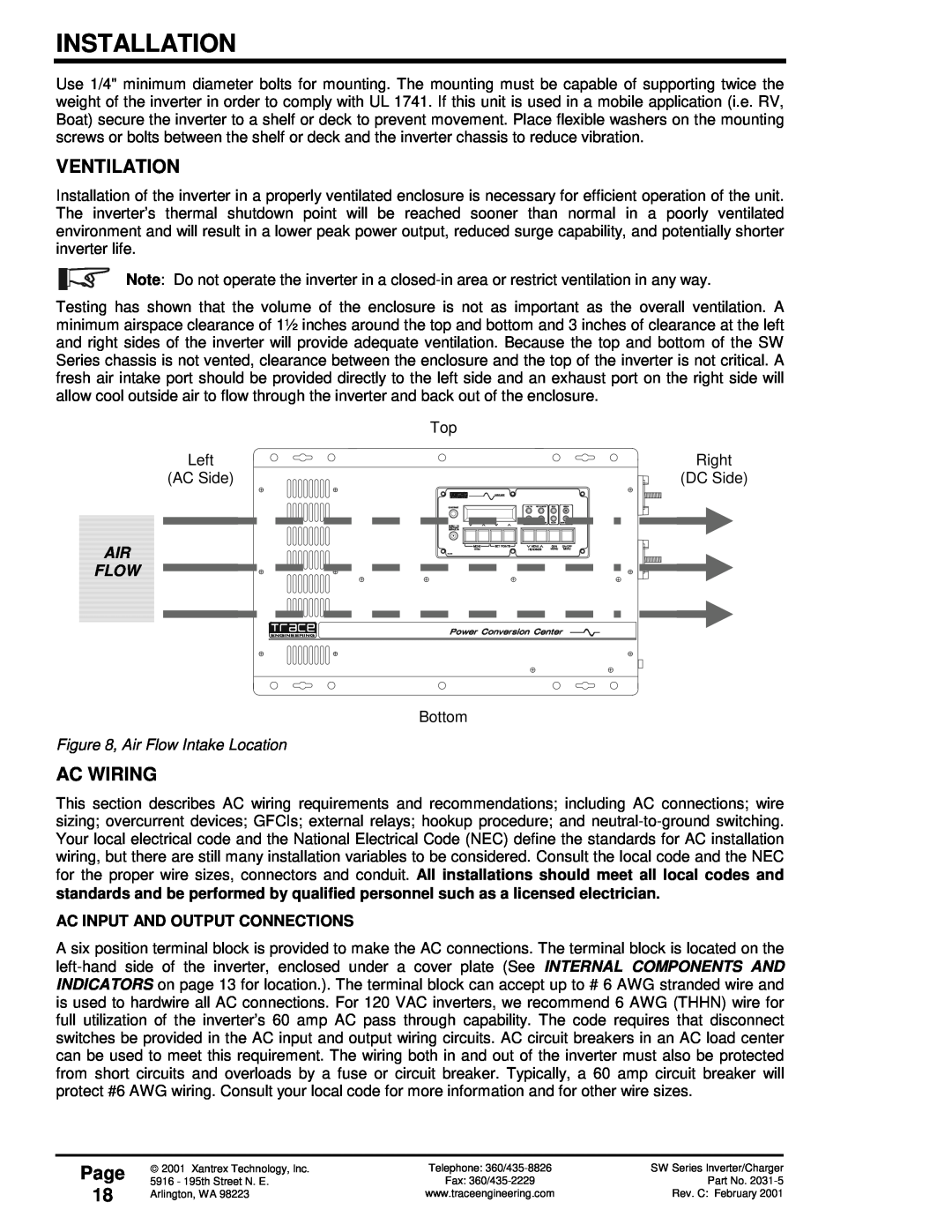
FLOW
AC WIRING
VENTILATION
Figure 8, Air Flow Intake Location
WIRE COLOR
Figure 9, AC Input/Output Power Connection
Table 1, AC Input and Output Wiring Connections
AC IN
EXTERNAL TRANSFER RELAYS
AC INSTALLATION GUIDELINES
IMPORTANT PRECAUTION
INSTALLATION
Figure 10, Warning Label
120 VAC GROUND FAULT INTERRUPT OUTLETS GFI’S
WARNING LABEL
INSTALLATION
Table 2, Minimum Recommended Battery Cable Size vs. Cable Length
DC WIRING
BATTERY CABLE SIZING
INVERTER MODEL
CABLE SIZE REQUIRED
Table 3, Battery Cable To Maximum Breaker/Fuse Size
DC DISCONNECT AND OVERCURRENT PROTECTION
RATING IN
INSTALLATION PROCEDURE - BATTERY CABLES
BATTERY CABLE CONNECTIONS
Figure 11, Battery to Inverter Cable Connection
INSTALLATION
AUX RELAY WIRING
CONTROL WIRING
GEN CONTROL WIRING
REMOTE CONTROL WIRING
GROUNDING ELECTRODES/GROUND RODS
SYSTEM GROUNDING
EQUIPMENT OR CHASSIS GROUNDS
BONDING THE GROUNDING SYSTEM
Page
NEUTRAL-TO-GROUND BOND SWITCHING RV AND MARINE APPLICATIONS
INSTALLATION
INSTALLATION
Figure 14, Neutral-To-Ground Bond Switching Neutral Bonded To Ground
AC SOURCE
Page
KEEP EQUIPMENT CLOSE TOGETHER
GROUNDING VS. LIGHTNING
ONE GROUND FOR ALL EQUIPMENT
Figure 15, Multiple Point Ground System
2001 Xantrex Technology, Inc
INSTALLATION
Page
Telephone 360/435-8826
FUNCTIONAL TEST FUNCTIONAL TEST
Page
2001 Xantrex Technology, Inc
FUNCTIONAL TEST
Page
Telephone 360/435-8826
Page
MENU SYSTEM MENU SYSTEM
OVERVIEW
MENU HEADINGS
MENU SYSTEM
USER MENU MAP
MENU ITEMS
MENU HEADINGS
SETUP MENU MAP
MENU SYSTEM
MENU ITEMS
MENU SYSTEM
USER MENU
MENU HEADINGS
Page
Move cursor to Inverter OFF to reset Overcurrent
INVERTER MODE 1 MENU HEADING
GENERATOR MODE 2 MENU HEADING
INFORMATION DISPLAY
Gen max run time errorNO
Generator start errorNO
Generator sync errorNO
MENU SYSTEM
MENU SYSTEM
TRACE ENGINEERING 3 MENU HEADING
5916 195th St NE Arlington, WA 98223 USA
Page
MENU SYSTEM
METERS 4 MENU HEADING
NOTE The meters do not display a + symbol for positive values
Page
MENU SYSTEM
ERROR CAUSES 5 MENU HEADING
AC1 & AC2 volts valid only when inverter synced to that input
Page
Page
Battery voltage was above the HIGH BATTERY CUT OUT VDC setting. This can be caused by the solar array or other charging source not being regulated. Check the controller for proper operation. Some controllers have a “equalize” setting which over-rides the normal operation, allowing the battery voltage to be unregulated. Return the controller to the “normal” setting and check for proper operation. If you are using NiCad type batteries, you will need to increase the HIGH BATTERY CUT OUT VDC setting. The inverter will automatically reset once the battery voltage has dropped 1.5 volts below the HBCO setting for a 12 VDC system, 3 volts for a 24 VDC system and 6 volts for a 48 VDC system
MENU SYSTEM
TIME OF DAY 6 MENU HEADING
GENERATOR TIMER 7 MENU HEADING
To defeat timers set start = end
Gen doesn’t run during quiet time unless batt volts is less than
MENU HEADINGS
SETUP MENU
MENU SYSTEM
Page
Page
INVERTER SETUP 9 MENU HEADING
MENU SYSTEM
Set Grid Usage FLT SELL SLT LBX
Page
This setting controls when the inverter turns off due to a low battery voltage condition. The inverter will turn off only after this level has been reached for the period of time set by the following item. When the automatic generator control system is used, the generator will be started when the battery voltage has dropped below this value for 30 seconds continuously. This will occur even during the quiet time period. This setting is not temperature compensated
MENU SYSTEM
MENU SYSTEM
BATTERY CHARGING 10 MENU HEADING
battery temperature if the BTS sensor is installed
Page
MENU SYSTEM
AC INPUTS 11 MENU HEADINGS
Sets the maximum amount of AC input current that the battery charger will use to charge the battery. This can be used to limit the charger output as well. The charger will “back-off” if the combination of AC loads and the charger reaches the AMPS AC setting of the AC INPUT connected to prevent overloading the source or tripping breakers. This process occurs automatically
Page
MENU SYSTEM
GEN AUTO START SETUP 12 MENU HEADING
Sets the AC load current that will initiate the automatic generator control system when the current remains above this setting continuously for the LOAD START DELAY MIN period
Page
Page
GEN STARTING DETAILS 13 MENU HEADING
MENU SYSTEM
INFORMATION DISPLAY
Page
AUXILIARY RELAYS 14 MENU HEADING
MENU SYSTEM
Set Pre Crank seconds10
MENU SYSTEM
Relays have 2 seconds delay on close, 0.1 sec delay on open
Close on batt setpoint. Open on batt setpoint - hys
Page
See menu 9 to enable LBX mode Make sure LBX is above LBCO volts
BULK CHARGE TRIGGER TIMER 15 MENU HEADING
LOW BATTERY TRANSFER 16 MENU HEADING
MENU SYSTEM
See menu 9 to enable SELL mode. Make sure LBX is above LBCO volts
BATTERY SELLING 17 MENU HEADING
GRID USAGE TIMER 18 MENU HEADING
SELL mode
MENU SYSTEM
INFORMATION FILE BATTERY 19 MENU HEADING
Sell and float modes use timer. SLT and LBX mode ignore timer
Page
2001 Xantrex Technology, Inc
MENU SYSTEM
Page
Telephone 360/435-8826
THEORY OF OPERATION
Figure 17, Trace SW Series Inverter Simple Block Diagram
OPERATION OPERATION
Page
Page
OPERATION
Figure 18, Trace SW Series Inverter Output Waveform
SW4024 / SW4048
POWER VS. EFFICIENCY
SW3024E / SW3048E
SW4548E
Temperature C
INVERTER CAPACITY VS TEMPERATURE
power
Figure 20, Inverter Capacity vs. Temperature
OPERATION
ADDITIONAL FEATURES
OPERATING MODES
Page
BATTERYDC
INVERTER MODE
SEARCH MODE CONTROL
SETTING SEARCH MODE WATTS
ADJUSTING THE LOW BATTERY PROTECTION
LOW BATTERY PROTECTION
SETTING SEARCH MODE SPACING
OPERATION
Figure 21, Three-Stage Battery Charging
CHARGER MODE
BATTERY
THREE STAGE CHARGING PROCESS
CHARGER ONLY OPERATION
BATTERY TEMPERATURE SENSOR BTS
Figure 22, BTS Battery Temperature Sensor
AC INPUT REQUIREMENTS
AC CURRENT LEVEL
RECOMMENDED BATTERY CHARGER SETTINGS
DELAY PERIOD
FREQUENCY
Battery Type
Table 4, Charging Setpoints For Common Battery Types
TYPICAL BULK AND FLOAT SETPOINTS FOR COMMON BATTERY TYPES
EQUALIZING BATTERIES UNSEALED OR VENTED BATTERIES ONLY
Page
To start the equalization process either manually or automatically
OPERATION
TRANSFERRING BASED ON BATTERY VOLTAGE
INVERTER/CHARGER MODE
TRANSFERRING UPON AVAILABILITY OF AC POWER
UTILITY GRID AC AC GENERATOR
OPERATION
TRANSFER TIME
While connected to the utility, the battery charger will be engaged. Some applications may want to allow the alternate power source solar, wind or hydro to recharge the battery instead of allowing the utility to provide the power. The only option is to program the SET MAX CHARGE AMPS AC menu item under the BATTERY CHARGING 10 menu heading to the minimum value, 1 amp AC, and set the BULK VOLTS and FLOAT VOLTS settings, also under the BATTERY CHARGING 10 menu heading, to a low value
Page
BATTERY
GENERATOR SUPPORT MODE
GENERATOR
OPERATION
OPERATION
GENERATOR SUPPORT/OVERLOAD PROTECTION
120 VAC VS. 120/240 VAC GENERATORS
Page
AC GENERATOR CONTROL
AUTOMATIC GENERATOR CONTROL MODE
DC BATTERY
INVERTER/ CHARGER
AUTOMATICALLY
GEN CONTROL RELAYS
GENERATOR STARTING SCENARIOS
OPERATION
OPERATION
GENERATOR STARTING AND STOPPING CONFIGURATIONS
MANUALLY
Page
Figure 23, Two Wire Start Wiring Diagram
TWO WIRE START GENERATORS
2 WIRE TYPE GENERATOR
GENERATOR AUTO START REQUIREMENTS AND TYPES
HONDA TYPE GENERATOR
THREE-WIRE START GENERATORS
Figure 25, Three-Wire Start Wiring Diagram ONAN Type
OPERATION
Figure 26, Relay RY7 and RY8 Sequence
3-TO-2 WIRE CONVERTERS
GENERATOR CONTROL SEQUENCE
OPERATION
OPERATION
GENERATOR ERROR CAUSES
GENERATOR STOP COOL DOWN PERIOD
Page
OPERATION
EQUALIZATION CHARGING, AUTOMATIC GENERATOR CONTROL SYSTEM
An automatic equalization charge process is available in the SW Series Inverter/Charger. To start the equalization process, select EQ from the SET GENERATOR menu item, accessible by pressing the green GEN MENU button on the Control Panel
Page
UTILITY GRID
UTILITY BACKUP MODE
GENERATOR AC INVERTER/ CHARGER DC BATTERY
MAIN
UTILITY SUPPORT/OVERLOAD PROTECTION
USING SLT MODE SILENT MODE
BATTERY REQUIREMENTS
OPERATION
UTILITY GRID kWh METER AC OUTDOOR AC DISCONNECT
UTILITY INTERACTIVE MODE
GROUND FAULT
MAIN AC LOADS AC NOT PROVIDEDSOLAR ARRAY WITH BACK-UP
When SELL mode is selected from the SET GRID USAGE menu item located under the INVERTER SETUP 9 menu heading in the SETUP MENU, the inverter will move any excess power not required to charge the batteries into the utility grid
THEORY OF OPERATION
UTILITY INTERACTIVE ISLANDING PROTECTION
OPERATION
DC Setting
SELLING POWER - FROM A DC CHARGING SOURCE
Battery Sell Volts
POSITIVE + = Inverter is drawing power from grid
OPERATION
SELLING POWER - STORED IN THE BATTERIES
Power stored in the batteries can also be sold into the utility grid. This can be used together with the solar array or alone without a solar array. The inverter can be programmed to sell the energy in the batteries at a specific time and then to recharge the batteries at another time. Both the discharge level and discharge rate can be adjusted to control the battery selling process
Page
BATTERY REQUIREMENTS
BATTERY REGULATION LEVEL - SELL MODE
15 menu heading is used to trigger a bulk charge cycle
OPERATION
UTILITY INTERACTIVE
UTILITY INTERACTIVE OPERATION WITH UTILITY BACKUP
BACKUP OF CRITICAL AC
LINE-TIE SYSTEM WITH
Figure 30, Overvoltage Protection for Battery
OVERVOLTAGE PROTECTION FOR THE BATTERY IN SELL MODE
BATTERY BANK
SOLAR ARRAY
OPERATION
ENERGY MANAGEMENT MODE
INVERTER/ CHARGER DC BATTERY
IN BRIEF
OPERATION
Page
INVERTER/ CHARGER DC BATTERY
PEAK LOAD SHAVING MODE
IN BRIEF
OPERATION
UTILITY GRID kWH METER AC AC LOADSAC MAIN PANEL
LOW BATTERY TRANSFER LBX MODE
SOLAR ARRAY DC GROUND FAULT PROTECTION
AC LOADS SUB-PANEL AC INVERTER CHARGER
Page
Once the system has transferred back to the battery, the battery voltage will continue to increase if the power from the alternative source exceeds the loads. This can result in the battery voltage reaching the HIGH BATTERY CUT OUT VDC setting unless a charge control device limits the battery voltage. Note that the LOW BATTERY CUT IN VDC setting must be set below the external charge controllers regulation setting or the system would never transfer back to the battery. The best compromise involves setting the BULK VOLTS DC equal to the FLOAT VOLTS DC default value, and setting the LOW BATTERY CUT IN VDC setting to the default BULK VOLTS DC setting. Make sure the external charge controller is set slightly higher than the LOW BATTERY CUT IN VDC setting so that the voltage can be reached without the charging source shutting off
OPERATION
“SERIES” STACKED OPERATION
USING MULTIPLE INVERTERS
INPUT/OUTPUT BYPASS BREAKER SWITCH - 240 VAC LOADS
OPERATION
240 VAC/60 HZ ONLY ELECTRICAL SYSTEMS
GENERATOR CONTROL SETTINGS
“PARALLEL” STACKED OPERATION
OPERATION
The inverters can operate in parallel as battery chargers from the same AC source connected to the same battery. The AC input terminals and DC terminals would all be in parallel. The inverters will synchronize individually to the AC source and then connect
BATTERY CHARGING WITH MULTIPLE INVERTERS
AUTOMATIC GENERATOR CONTROL WITH MULTIPLE INVERTERS
OPERATION
2001 Xantrex Technology, Inc
OPERATION
Page
Telephone 360/435-8826
STARTING BATTERY
BATTERY TYPE
SELECTION OF BATTERY TYPE
TELEPHONE COMPANY BATTERY
Page 100
NICAD AND NICKEL IRON NIFE BATTERY
TECHNICAL INFORMATION
SEALED LEAD ACID BATTERIES
Page 101
BATTERY SIZING
ESTIMATING BATTERY REQUIREMENTS
Table 5, Typical Wattage Of Common Appliances
Page 102
BATTERY BANK SIZING
EXAMPLE
5,139
TECHNICAL INFORMATION
WORKSHEET
Page 103
WATTS
Page 104
BATTERY CARE AND MAINTENANCE
Table 6, Battery Charging Charging Setpoints
TYPICAL BULK AND FLOAT SETPOINTS FOR COMMON BATTERY TYPES
Table 7, Battery State of Charge Voltage
MONTHLY MAINTENANCE
BATTERY STATE OF CHARGE
Page 105
BATTERY TEMPERATURE
BATTERY INSTALLATION
BATTERY ENCLOSURES
Page 106
Figure 31, Series Configuration 6-Volt Battery Wiring
BATTERY HOOK-UP CONFIGURATIONS
Each individual 6-volt battery capacity = 100 amp hours
Total Battery Capacity
PARALLEL CONNECTION
Each individual 12-volt battery capacity = 50 amp hours
Figure 33, Parallel Configuration 12-Volt Battery Wiring
SERIES - PARALLEL CONNECTION
Page 109
Total Battery Capacity
Figure 35, Series-Parallel Configuration 12-Volt Battery Wiring
6V 6V
Table 8, Battery Cable Inductance
BATTERY CABLE INDUCTANCE
Distance Between Battery Cables Inductance in micro-Henries
Page 110
INDUCTIVE LOADS
APPLICATIONS
RESISTIVE LOADS
Page 111
PROBLEM
TROUBLESHOOTING GUIDE
INVERTER - If ERROR LED comes on, see ERROR CAUSES section
SOLUTION
Page
BATTERY CHARGER - If ERROR LED comes on, see ERROR CAUSES section
Page 113
TROUBLESHOOTING GUIDE
SOLUTION
Page 114
TROUBLESHOOTING GUIDE
TECHNICAL INFORMATION
Digital VoltMeter DVM
INVERTER/CHARGER TERMINOLOGY
Page 115
TECHNICAL INFORMATION
TECHNICAL INFORMATION
Page 116
Figure 36, AC Waveforms
TECHNICAL INFORMATION
Page 117
Stacking
Page 118
SPECIFICATIONS AND FEATURES 60 Hz Models
Note All specifications are subject to change without notice
MODEL
SW2612E
SPECIFICATIONS AND FEATURES 50 Hz Models
Page 119
SW3024E SW3048E SW4548E SW3024J SW4048J SW4548A
TECHNICAL INFORMATION
DIMENSIONS
Page 120
2001 Xantrex Technology, Inc
TECHNICAL INFORMATION
INSTALLATION DIAGRAMS
Page 121
2001 Xantrex Technology, Inc
Page 122
TECHNICAL INFORMATION
Telephone 360/435-8826
Page 123
USER SETTINGS WORKSHEETS
USER MENU
SW Series Inverter/Charger - Model SW
DEFAULT SETTINGS
SETUP MENU - 12 VDC 120 VAC/60HZ MODELS
Page 124
USER SETTINGS
DEFAULT SETTINGS
SETUP MENU - 24 VDC 120 VAC/60HZ MODELS
Page 125
USER SETTINGS
DEFAULT SETTINGS
SETUP MENU - 48 VDC 120 VAC/60HZ MODELS
Page 126
USER SETTINGS
2001 Xantrex Technology, Inc
Page 127
TECHNICAL INFORMATION
Telephone 360/435-8826
SWRC
APPENDIX
OPTIONS
SWCA
OTHER PRODUCTS
SW SERIES POWER PANEL SYSTEMS
TM500 TRACE METER BATTERY STATUS MONITOR
C40 MULTI-FUNCTION CONTROLLER
REFERENCE TABLES AND GRAPHS
Table 9, Power Consumption Of Common Appliances
Table 10, AWG to Metric Wire Conversion Chart
Page 130
Page 131
Table 11, Minimum Recommended Battery Cable Size vs. Cable Length
Table 12, Battery Cable to Maximum Breaker/Fuse Size
NEC AMPS2
Battery DC Disconnect Size
Table 13, Recommended Minimum AC Wire Sizes 75 C
Table 15, Safety Ground Wire Size Table
Minimum Size of Copper Ground Wire
Page 133
Storage Checklist
Preparation for Storage
Interior Storage
2001 Xantrex Technology, Inc
Page 134
APPENDIX
Telephone 360/435-8826
WARRANTY REGISTRATION
WARRANTY/REPAIR INFORMATION WARRANTY/REPAIR INFORMATION
LIMITED WARRANTY
LIFE SUPPORT POLICY
Page 136
WARRANTY/REPAIR INFORMATION
WARRANTY OR REPAIR SERVICE REQUIRED
Hook Up Configurations
INDEX
Page 137
INDEX
Page
INDEX
INDEX
Page 139
Low Battery Cut Out VDC
Output Waveform
INDEX
Page
INDEX
Page 141
Installation Guidelines
Stored In The Batteries
Page 142
INDEX