Configuring the System
Menu map
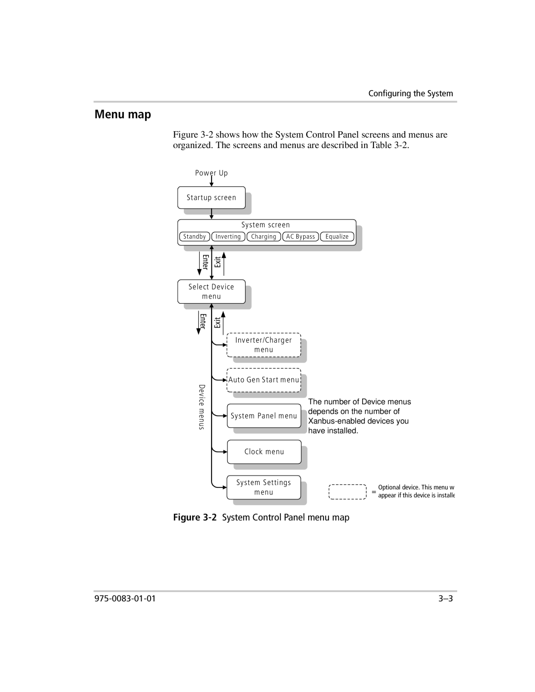
Figure 3-2 shows how the System Control Panel screens and menus are organized. The screens and menus are described in Table 3-2.
Pow er Up
Startup screen
Sy stem screen
Standby Inverting Charging AC Bypass Equalize
Enter
Exit
Select Dev ice
m enu
Enter
Device m enus
Exit
Inv erter/Charger
m enu
![]() Auto Gen Start m enu
Auto Gen Start m enu
![]() Sy stem Panel m enu
Sy stem Panel m enu
Clock m enu
Sy stem Settings
m enu
The number of Device menus depends on the number of
=Optional device. This menu w appear if this device is installe
