Freedom SW 3000 Inverter/Charger Features
Front and Side Panels
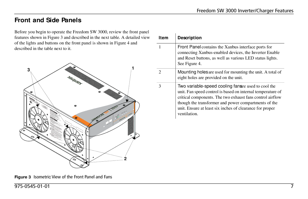
Before you begin to operate the Freedom SW 3000, review the front panel features shown in Figure 3 and described in the next table. A detailed view of the lights and buttons on the front panel is shown in Figure 4 and described in the table next to it.
3 | 1 |
|
3000W | SINEWA |
|
|
|
|
|
| FREE |
|
|
| ||
| VE | DOM |
|
| ||
|
| INVER |
| SW | 3000 | |
|
|
|
|
|
| |
|
|
| TER/CHARGER | |||
Item | Description |
1 | Front Panel contains the Xanbus interface ports for |
| connecting |
| and Reset buttons, as well as various LED status lights. |
| See Figure 4. |
|
|
2 | Mounting holes are used for mounting the unit. A total of |
| eight holes are provided on the unit. |
|
|
3 | Two |
| unit. Fan speed control is based on internal temperature of |
| critical components. The two exhaust fans control airflow |
| though the transformer and power compartments of the |
Model
Number
FGA
Number
FSW3000 815- 3000
Inverter |
|
|
|
|
|
|
|
|
|
|
|
|
|
| ||
Nominal |
|
|
|
|
|
|
|
|
|
|
|
|
|
|
| |
Nominal DCMode: |
|
|
|
|
|
|
|
|
|
|
| |||||
MaxNominal. | AC | OutputOperating |
|
|
|
|
|
|
|
|
|
| ||||
Max. |
| AC |
|
|
|
|
|
|
|
|
|
| ||||
Max.ContinuousOutput |
|
|
|
| 12 |
|
|
|
|
|
| |||||
| Operating | ACVoltage:Voltage: |
|
|
|
|
|
| ||||||||
Max.Continuous3000 | ACInputFrequency:Output | 60Vac |
|
|
|
|
|
| ||||||||
MaxInput:. |
|
| DC |
|
|
| 120 | Vdc |
|
|
|
|
| |||
Max.DCOutput | VA at |
|
|
|
| Hz |
| ,1Ø |
|
|
| |||||
|
| InputSurge | 25°COutputCurrent:Current:at | 25 A |
|
|
|
| ||||||||
| Ambient |
|
| Power | (5s |
| 320 A |
|
|
|
|
| ||||
Charger |
| Voltage: |
| Nominal |
|
|
|
|
| |||||||
Power |
| ACMode:Temperature: |
| 5duration): |
|
|
|
|
| |||||||
Nominal |
|
|
|
|
| 16 | Vdc |
|
|
| DC |
|
|
|
| |
MaxCharging. Factor:Input |
|
|
| 0°C |
| 6000 VA |
|
| ||||||||
|
| DC | > | 0.Voltage:95 | 120 |
|
|
|
| |||||||
MaxNominal.ContinuousOutput |
|
|
|
|
|
|
|
|
| |||||||
30 | AC |
| AC |
|
| Voltage |
| Vac |
|
|
|
|
|
| ||
A |
| Input |
|
|
| ,60 |
|
|
|
| ||||||
| per line | Input:Battery |
|
|
| Hz, |
|
|
| |||||||
|
|
|
| DualCurrent:150 AChargerRange: |
|
|
|
|
| |||||||
INSTALLATIONspecified ininv |
|
| line | SplitCurrent atVdc |
|
| ||||||||||
Mount | this |
|
|
| 30 A |
| per |
| 1Ø |
|
| |||||
|
|
|
|
|
|
|
|
|
|
| .0 |
|
|
| ||
CAUTION:incovera or erter/chargerinst |
|
|
| Phase, |
|
|
| |||||||||
user |
|
| the |
|
|
|
|
|
|
|
|
|
|
| ||
| clearancenot ventilationREQUIREMENTS:the |
| ||||||||||||||
resultzero. - |
|
| To allation | only |
|
|
|
|
|
| ||||||
|
|
| Doobstruct | reduce | guidein the |
|
|
|
|
| ||||||
WARNING:DC expose to |
|
| riskprovidedof orientations. |
| ||||||||||||
Usesourcesserviceable | compartme . |
| .fire, | do |
|
|
| |||||||||
|
| only . |
| Shock | rainopeningsnt |
|
|
|
| |||||||
typesspecified groundin Disconnect- | hazard.spray. |
| Do | not |
|
| ||||||||||
|
|
|
|
|
| parts. |
|
| or |
|
| not |
| |||
this | may | the | fault |
|
|
| DoOverheatingmount | |||||||||
lead- |
|
| fail to |
|
| Energized | not |
|
| may | ||||||
|
| equipmentacid .installationcircuitsourcesfrom |
| open. | No |
| ||||||||||
causing |
|
|
| operate |
|
|
|
| both | AC |
| |||||
|
|
| batteriesRefer. | to proguideinterruptersbefore |
|
| g. | |||||||||
DANGER:in |
| Other |
| perly | supplied(GFCI). |
| ||||||||||
install | personal | injury |
|
|
|
|
| servicinand | ||||||||
|
|
| an |
|
| manualb .when |
| Other |
| |||||||
euipment is areaTo |
|
| and |
| ttery |
|
|
|
| |||||||
|
|
|
| requi | inreduce |
|
| Chargeconnecte |
| |||||||
|
|
|
|
|
| redwhich. |
| risk |
|
| may | burst | to | |||
|
|
|
|
|
|
|
|
|
|
|
| |||||
|
|
|
|
|
|
|
|
|
|
| protecteexplosion, | do not | ||||
|
|
|
|
|
|
|
|
|
|
|
|
|
|
| ||
Serial | Number |
|
Designed
AssembledininCanada
China
Date of | Manufacture |
|
SW FREEDOM
Xanbus
3000
|
| AC/ Fault | |
| er | Cha | rge |
In | vert |
| |
On |
|
| |
ter |
|
|
|
Inver |
|
|
|
Enable |
|
| SW |
Reset |
|
| |
FREEDOM | |||
rface Inte
![]() 3000
3000
unit. Ensure at least six inches of clearance for proper |
ventilation. |
2
Figure 3 Isometric View of the Front Panel and Fans
7 |