Control panel
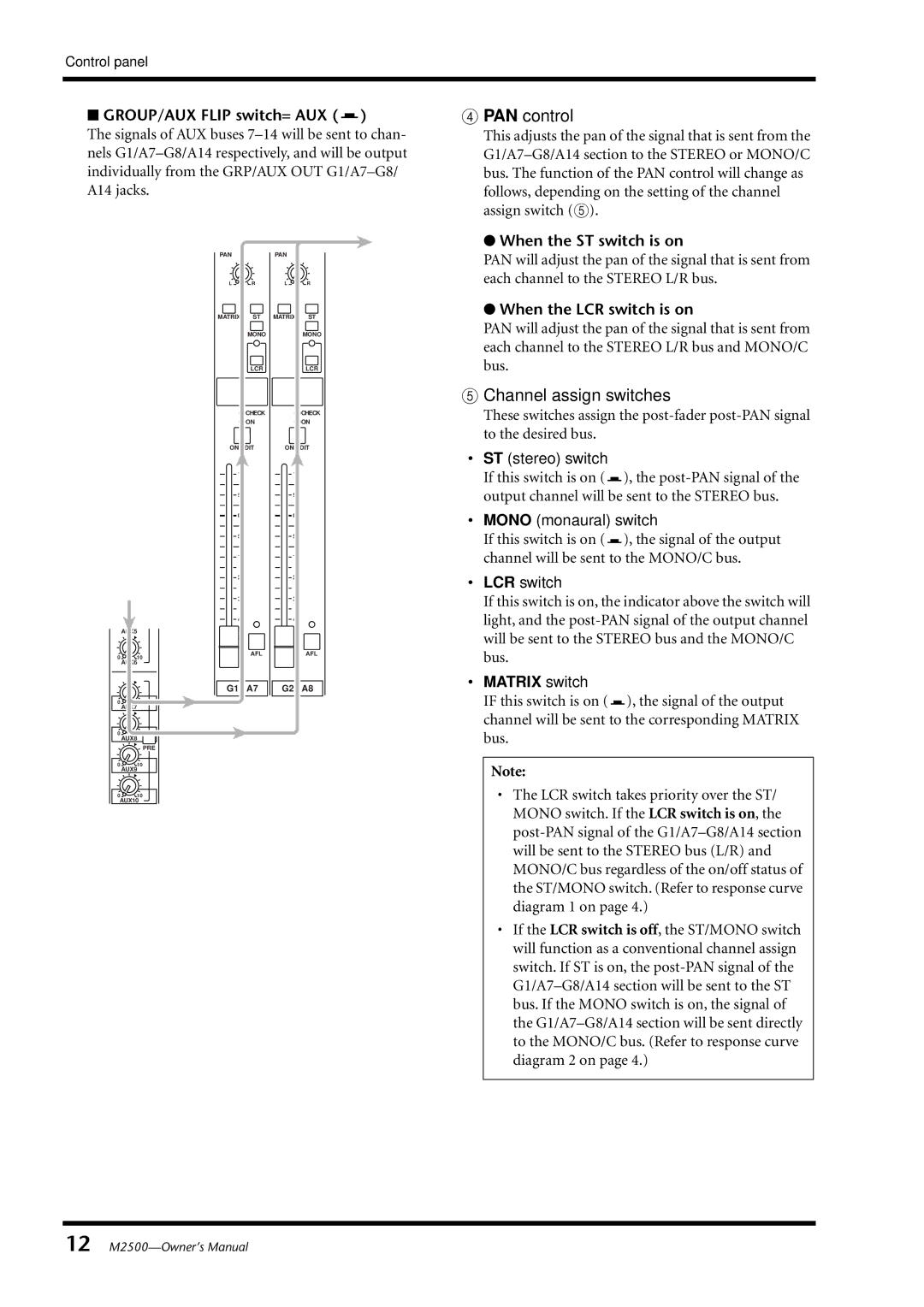
■GROUP/AUX FLIP switch= AUX ( )
)
The signals of AUX buses
| PAN |
| PAN |
|
| C |
| C |
|
| L | R | L | R |
| MATRIX | ST | MATRIX | ST |
|
| MONO |
| MONO |
|
| LCR |
| LCR |
|
| CHECK |
| CHECK |
|
| ON |
| ON |
| ON/EDIT | ON/EDIT | ||
| 10 |
| 10 |
|
| 5 |
| 5 |
|
| 0 |
| 0 |
|
| 5 |
| 5 |
|
| 10 |
| 10 |
|
| 20 |
| 20 |
|
| 30 |
| 30 |
|
| 40 |
| 40 |
|
| 50 |
| 50 |
|
| 60 |
| 60 |
|
0 | 10 | AFL |
| AFL |
|
|
| ||
| AUX6 |
|
|
|
| G1 / A7 | G2 / A8 | ||
010
AUX7
010
AUX8
PRE
010
AUX9
010
AUX10
D PAN control
This adjusts the pan of the signal that is sent from the
●When the ST switch is on
PAN will adjust the pan of the signal that is sent from each channel to the STEREO L/R bus.
●When the LCR switch is on
PAN will adjust the pan of the signal that is sent from each channel to the STEREO L/R bus and MONO/C bus.
E Channel assign switches
These switches assign the
•ST (stereo) switch
If this switch is on (![]() ), the
), the
•MONO (monaural) switch
If this switch is on (![]() ), the signal of the output channel will be sent to the MONO/C bus.
), the signal of the output channel will be sent to the MONO/C bus.
•LCR switch
If this switch is on, the indicator above the switch will light, and the
•MATRIX switch
IF this switch is on (![]() ), the signal of the output channel will be sent to the corresponding MATRIX bus.
), the signal of the output channel will be sent to the corresponding MATRIX bus.
Note:
•The LCR switch takes priority over the ST/ MONO switch. If the LCR switch is on, the
•If the LCR switch is off, the ST/MONO switch will function as a conventional channel assign switch. If ST is on, the
12