Control panel
GROUP/AUX FLIP switch
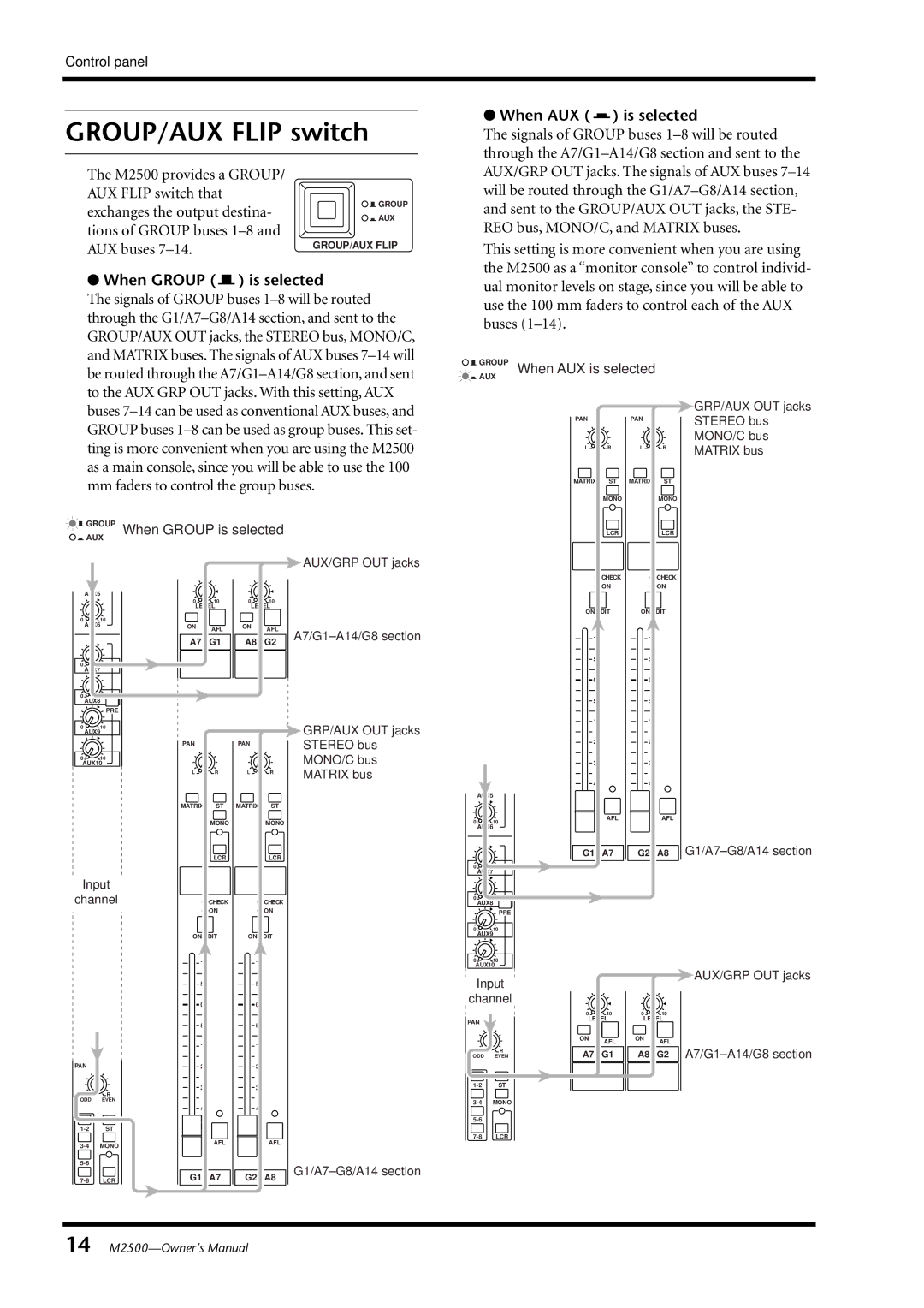
The M2500 provides a GROUP/
AUX FLIP switch that
exchanges the output destina- | GROUP | |
AUX | ||
tions of GROUP buses | GROUP/AUX FLIP | |
AUX buses | ||
|
●When GROUP ( ) is selected
The signals of GROUP buses
| GROUP | When GROUP is selected |
| |||
| AUX |
|
|
|
|
|
|
|
|
|
|
| AUX/GRP OUT jacks |
|
| 0 | 10 | 0 | 10 |
|
|
| LEVEL | LEVEL |
| ||
0 | 10 |
|
|
|
|
|
| AUX6 | ON | AFL | ON | AFL | |
|
|
|
| |||
|
| A7 / G1 | A8 / G2 | |||
|
|
| ||||
010
AUX7
010
AUX8
PRE
0 | 10 |
|
|
| GRP/AUX OUT jacks |
| AUX9 |
|
|
| |
| PAN | C | PAN |
| STEREO bus |
|
| C |
| ||
0 | 10 |
|
|
| MONO/C bus |
AUX10 |
|
|
| ||
| L | R | L | R | MATRIX bus |
|
|
|
|
| |
| MATRIX | ST | MATRIX | ST |
|
|
| MONO |
| MONO |
|
|
| LCR |
| LCR |
|
Input |
|
|
|
| |
channel | CHECK |
| CHECK |
| |
|
| ON |
| ON |
|
●When AUX ( ) is selected
The signals of GROUP buses
This setting is more convenient when you are using the M2500 as a “monitor console” to control individ- ual monitor levels on stage, since you will be able to use the 100 mm faders to control each of the AUX buses

 GROUP When AUX is selected
![]()
![]() AUX
AUX
|
|
|
| GRP/AUX OUT jacks |
C |
| C |
| STEREO bus |
PAN |
| PAN |
|
|
|
|
|
| MONO/C bus |
L | R | L | R | MATRIX bus |
MATRIX | ST | MATRIX | ST |
|
| MONO |
| MONO |
|
| LCR |
| LCR |
|
| CHECK |
| CHECK |
|
| ON |
| ON |
|
ON/EDIT | ON/EDIT |
| ||
10 |
| 10 |
|
|
5 |
| 5 |
|
|
0 |
| 0 |
|
|
5 | 5 |
10 | 10 |
20 | 20 |
30 | 30 |
40 | 40 |
50 | 50 |
60 | 60 |
0 | AFL | AFL |
10 |
|
AUX6
G1 / A7 | G2 / A8 |
010
AUX7
010
AUX8
PRE
ON/EDIT |
|
| ON/EDIT | ||||
10 |
| 10 | |||||
| |||||||
|
|
|
|
|
|
|
|
5 |
|
| 5 |
| |||
|
|
| |||||
010
AUX9
010
AUX10
Input
AUX/GRP OUT jacks
|
|
|
| 0 |
|
|
| 0 | ||
|
|
|
|
|
|
|
|
|
|
|
|
|
| 5 |
|
| 5 | ||||
|
|
|
|
|
|
|
|
|
|
|
PAN |
|
| 10 |
| 10 | |||||
|
|
| ||||||||
C |
|
| 20 | |||||||
| 20 |
| ||||||||
|
| |||||||||
|
|
|
|
|
|
|
|
|
| |
|
|
|
|
|
|
|
|
|
|
|
3030
LR
ODD EVEN
|
| 40 | 40 |
| |
|
| 50 | 50 |
| |
ST | 60 | 60 |
| ||
|
|
| |||
MONO | AFL | AFL |
| ||
|
|
| |||
|
|
| |||
LCR | G1 / A7 | G2 / A8 | |||
|
channel
|
| 0 | 10 | 0 | 10 |
PAN |
| LEVEL | LEVEL | ||
|
|
|
|
| |
|
| ON | AFL | ON | AFL |
|
|
|
| ||
L | R | A7 / G1 | A8 / G2 | ||
ODD | EVEN | ||||
14