Control panel
Stereo input channels
GAIN
A
| 1 |
+10 | |
B |
|
| 2 |
+10 | |
B | 3 |
A |
|
HI
LO4
![]() 5
5
EQ
010
AUX1 PRE
010
AUX2
0 | 10 |
|
|
|
AUX3 |
|
|
| |
|
| 0 | 10 |
|
|
| AUX14 |
| |
0 | 10 |
|
|
|
AUX4 | BAL |
|
| |
| PRE |
|
| |
|
|
|
| |
0 | 10 |
|
| 8 |
AUX5 | L | R |
| |
|
| ODD | EVEN |
|
0 | 10 |
|
|
|
AUX6 | ST |
| ||
6 |
|
| ||
| MONO | 9 | ||
|
| |||
0 | 10 |
|
| |
AUX7 |
|
|
| |
|
|
|
| |
0 | 10 | 7 |
|
|
AUX8 |
|
| ||
|
|
| ||
| PRE |
|
|
|
0 | 10 |
| CHECK |
|
AUX9 |
| ON |
| |
|
|
| J | |
|
|
|
| |
0 | 10 | ON/EDIT |
| |
AUX10 |
|
|
| |
0 | 10 |
| 10 PEAK |
|
AUX11 |
|
| K | |
|
|
| 5 NOM | |
0 | 10 |
| SIGNAL |
|
AUX12 |
|
| ||
|
|
| 0 |
|
| PRE |
|
|
|
0 | 10 |
| 5 |
|
AUX13 |
|
|
| |
|
|
| 10 |
|
0 | 10 |
|
|
|
AUX14 |
| 20 |
| |
|
|
|
| |
BAL | C |
|
|
|
|
| 30 |
| |
|
|
|
| |
L | R |
| 40 |
|
ODD | EVEN |
| 50 |
|
L | 60 | M |
|
| PFL |
The M2500 provides four stereo input channels, allowing
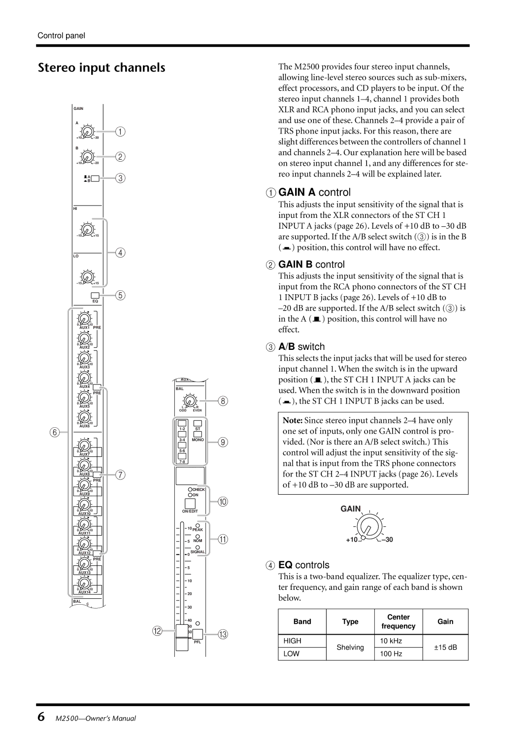
A GAIN A control
This adjusts the input sensitivity of the signal that is input from the XLR connectors of the ST CH 1 INPUT A jacks (page 26). Levels of +10 dB to ![]() ) position, this control will have no effect.
) position, this control will have no effect.
B GAIN B control
This adjusts the input sensitivity of the signal that is input from the RCA phono connectors of the ST CH 1 INPUT B jacks (page 26). Levels of +10 dB to ![]() ) position, this control will have no effect.
) position, this control will have no effect.
CA/B switch
This selects the input jacks that will be used for stereo input channel 1. When the switch is in the upward position (![]() ), the ST CH 1 INPUT A jacks can be used. When the switch is in the downward position (
), the ST CH 1 INPUT A jacks can be used. When the switch is in the downward position (![]() ), the ST CH 1 INPUT B jacks can be used.
), the ST CH 1 INPUT B jacks can be used.
Note: Since stereo input channels
GAIN
+10
D EQ controls
This is a
Band | Type | Center | Gain | |
frequency | ||||
|
|
| ||
|
|
|
| |
HIGH | Shelving | 10 kHz | ±15 dB | |
|
| |||
LOW | 100 Hz | |||
|
| |||
|
|
|
|
6