Talkback/oscillator section
| PINK |
|
1 | 10kHz |
|
| 1kHz |
|
| 100Hz |
|
2 | ON | 6 |
| ||
| OSCILLATOR | 7 |
|
|
![]()
![]() 8
8
Control panel
F AUX
G AUX
H AUX
I AUX
J ST switch
K MONO/C switch
These switches send the talkback or oscillator signal to AUX buses
![]() 9
9
3![]()
![]()
![]() J
J
MICST
AUX
1 3 5 7 9 11 13
2 4 6 8 10 12 14
STEREO L R
MONO/C
4![]()
![]()
![]() K
K
MONO/C
010
TB/OSC
5
ON
TALKBACK
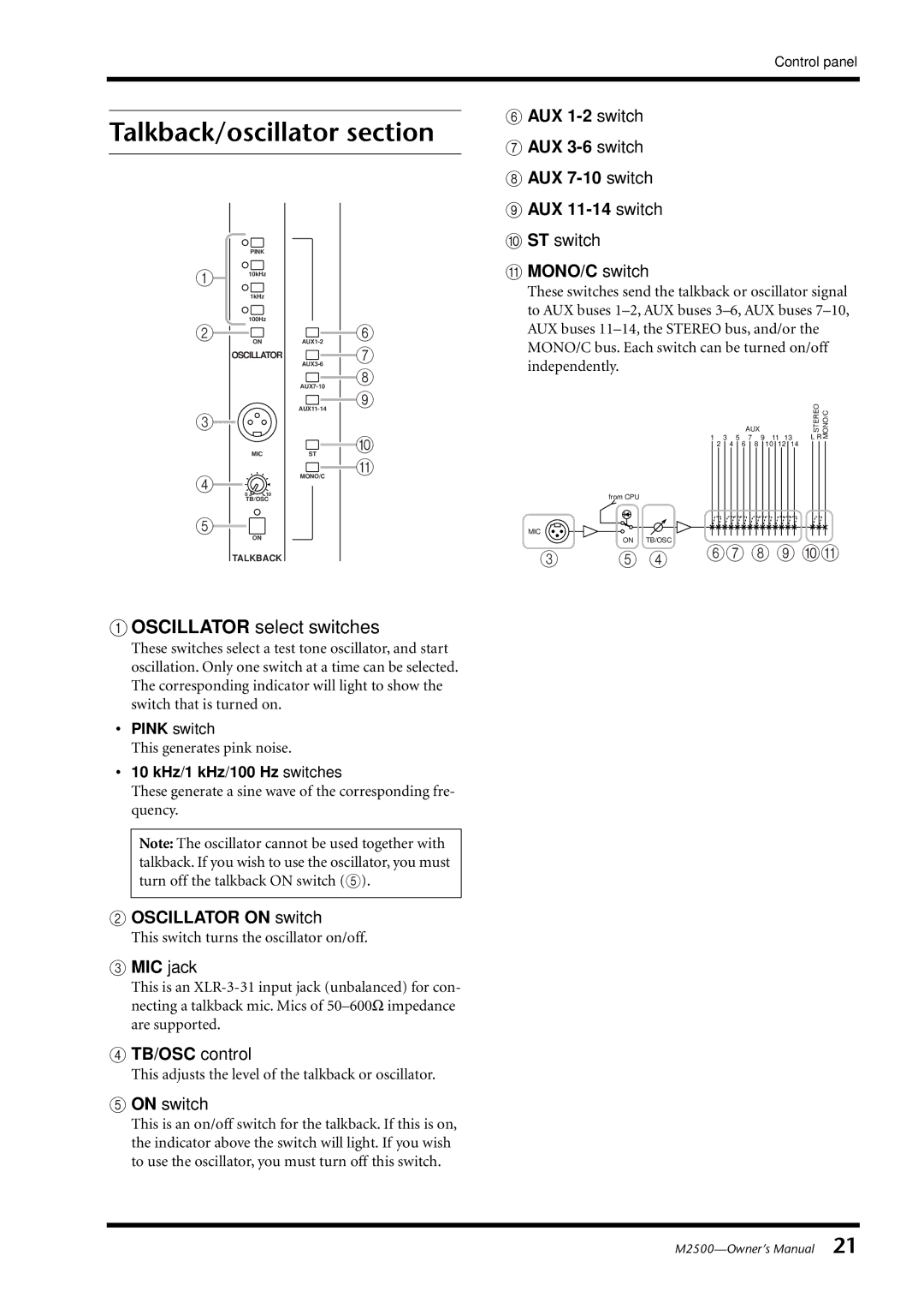
A OSCILLATOR select switches
These switches select a test tone oscillator, and start oscillation. Only one switch at a time can be selected. The corresponding indicator will light to show the switch that is turned on.
•PINK switch
This generates pink noise.
•10 kHz/1 kHz/100 Hz switches
These generate a sine wave of the corresponding fre- quency.
Note: The oscillator cannot be used together with talkback. If you wish to use the oscillator, you must turn off the talkback ON switch (5).
B OSCILLATOR ON switch
This switch turns the oscillator on/off.
C MIC jack
This is an
D TB/OSC control
This adjusts the level of the talkback or oscillator.
E ON switch
This is an on/off switch for the talkback. If this is on, the indicator above the switch will light. If you wish to use the oscillator, you must turn off this switch.
from CPU
MIC
ON TB/OSC
3 | 5 4 | 67 8 9 JK |
|