Control panel
Meter bridge
|
|
|
|
|
|
|
|
|
|
|
|
|
| 1 |
|
|
|
|
|
|
|
|
|
|
|
|
| 2 |
|
|
|
|
|
|
|
| 4 |
|
|
|
|
|
| |||||
|
| 7 | 5 | 3 | PEAK |
|
| 7 | 5 | 3 | PEAK |
|
| 7 | 3 | PEAK |
|
| 7 | 5 | 3 | PEAK |
|
| 7 | 5 | 3 | PEAK | +15V |
|
| 7 | 5 | 3 | PEAK |
|
| 7 | 5 | 3 | PEAK |
|
| 7 | 5 | 3 | PEAK | |
| 10 | 10 |
| 10 | 10 |
| 10 | 10 |
| 10 | 10 |
| 10 | 10 |
| 10 | 10 |
| 10 | 10 |
| 10 | 10 | |||||||||||||||||||||||||
20 | 20 | 20 | 20 | 20 | 20 | 20 | 20 | |||||||||||||||||||||||||||||||||||||||||
|
|
|
| 3 |
|
|
|
| 3 |
|
|
| 3 |
|
|
|
| 3 |
|
|
|
| 3 |
|
|
|
| 3 |
|
|
|
| 3 |
|
|
|
| 3 | ||||||||||
|
|
| VU | + |
|
|
| VU | + |
|
|
| V U | + |
|
|
| VU | + |
|
|
| VU | + | +12V |
|
|
| VU | + |
|
|
| VU | + | – |
|
| VU | + | ||||||||
|
|
|
|
|
|
|
|
|
|
|
|
|
|
| PHANTOM MASTER |
|
|
|
|
|
|
|
| |||||||||||||||||||||||||
|
|
|
|
|
|
|
|
|
|
|
|
|
|
|
|
|
|
|
|
|
|
|
|
|
|
|
|
|
|
|
| |||||||||||||||||
|
|
| 1/7 |
|
|
|
| 2/8 |
|
|
|
|
|
|
|
| 7/13 |
|
|
| 8/14 |
|
|
| STEREO L |
| MONO/C |
| STEREO R | |||||||||||||||||||
|
|
|
|
|
|
|
|
|
|
|
|
|
|
|
|
|
|
|
|
|
|
|
|
|
|
|
|
|
|
| PFL/AFL L |
|
|
|
|
|
|
| PFL/AFL R | |||||||||
|
|
|
|
|
|
|
|
|
|
|
|
|
|
|
|
|
|
|
|
|
|
|
|
|
|
|
|
| 3 |
|
|
|
|
|
|
|
| 5 |
|
|
|
|
|
| ||||
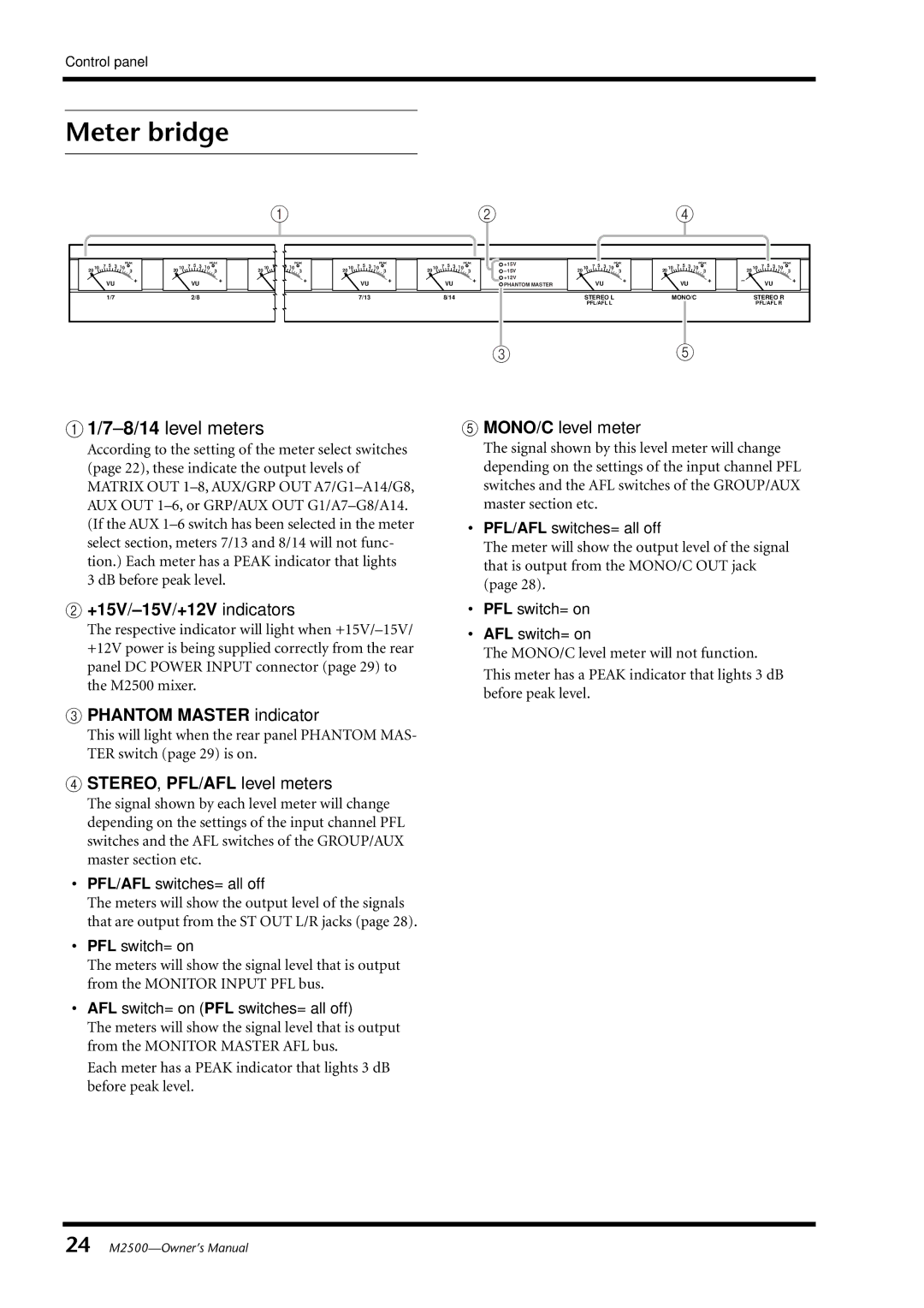
A 1/7–8/14 level meters
According to the setting of the meter select switches (page 22), these indicate the output levels of MATRIX OUT
B+15V/–15V/+12V indicators
The respective indicator will light when
E MONO/C level meter
The signal shown by this level meter will change depending on the settings of the input channel PFL switches and the AFL switches of the GROUP/AUX master section etc.
•PFL/AFL switches= all off
The meter will show the output level of the signal that is output from the MONO/C OUT jack (page 28).
•PFL switch= on
•AFL switch= on
The MONO/C level meter will not function. This meter has a PEAK indicator that lights 3 dB before peak level.
C PHANTOM MASTER indicator
This will light when the rear panel PHANTOM MAS- TER switch (page 29) is on.
D STEREO, PFL/AFL level meters
The signal shown by each level meter will change depending on the settings of the input channel PFL switches and the AFL switches of the GROUP/AUX master section etc.
•PFL/AFL switches= all off
The meters will show the output level of the signals that are output from the ST OUT L/R jacks (page 28).
•PFL switch= on
The meters will show the signal level that is output from the MONITOR INPUT PFL bus.
•AFL switch= on (PFL switches= all off)
The meters will show the signal level that is output from the MONITOR MASTER AFL bus.
Each meter has a PEAK indicator that lights 3 dB before peak level.
24
