Control panel
Matrix section
The M2500 provides an eight channel matrix section that allows the output signals from the
![]()
![]() 1
1
00
L SUB IN R
![]()
![]() 2
2
00
L ST R
3
0![]()
MONO/C
0![]()
G1 / A7
0![]()
G2 / A8
0![]()
G3 / A9
0 | 4 |
G4 / A10 |
0![]()
G5 / A11
0![]()
G6 / A12
0![]()
G7 / A13
0![]()
G8 / A14
| 5 |
0 | 10 |
LEVEL | |
6 | 7 |
ON | AFL |
| |
MATRIX 1
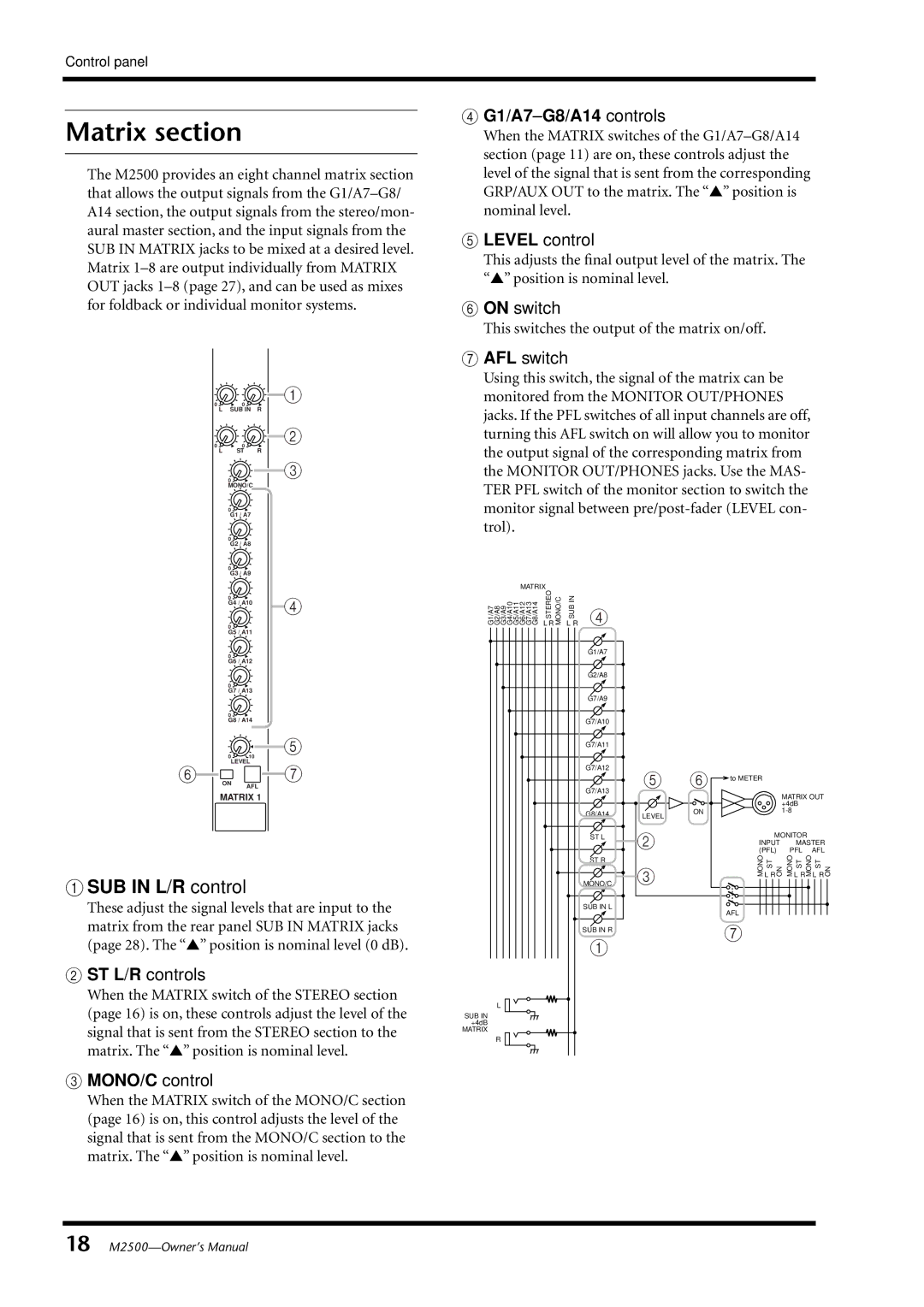
A SUB IN L/R control
These adjust the signal levels that are input to the matrix from the rear panel SUB IN MATRIX jacks (page 28). The “▲” position is nominal level (0 dB).
BST L/R controls
When the MATRIX switch of the STEREO section (page 16) is on, these controls adjust the level of the signal that is sent from the STEREO section to the matrix. The “▲” position is nominal level.
CMONO/C control
When the MATRIX switch of the MONO/C section (page 16) is on, this control adjusts the level of the signal that is sent from the MONO/C section to the matrix. The “▲” position is nominal level.
DG1/A7–G8/A14 controls
When the MATRIX switches of the
ELEVEL control
This adjusts the final output level of the matrix. The “▲” position is nominal level.
FON switch
This switches the output of the matrix on/off.
GAFL switch
Using this switch, the signal of the matrix can be monitored from the MONITOR OUT/PHONES jacks. If the PFL switches of all input channels are off, turning this AFL switch on will allow you to monitor the output signal of the corresponding matrix from the MONITOR OUT/PHONES jacks. Use the MAS- TER PFL switch of the monitor section to switch the monitor signal between
MATRIX |
|
|
|
|
|
|
| |
G1/A7 G2/A8 G3/A9 G4/A10 G5/A11 G6/A12 G7/A13 G8/A14 | STEREO | SUBIN |
|
|
|
|
|
|
L RMONO/C | L R 4 |
|
|
|
|
|
| |
|
| G1/A7 |
|
|
|
|
|
|
|
| G2/A8 |
|
|
|
|
|
|
|
| G7/A9 |
|
|
|
|
|
|
|
| G7/A10 |
|
|
|
|
|
|
|
| G7/A11 |
|
|
|
|
|
|
|
| G7/A12 | 5 | 6 |
|
|
|
|
|
| G7/A13 | to METER |
|
|
| ||
|
|
|
|
|
| MATRIX OUT | ||
|
|
|
|
|
|
| ||
|
|
|
|
|
|
| +4dB |
|
|
| G8/A14 | LEVEL | ON |
|
|
| |
|
|
|
|
|
|
| ||
|
|
|
|
|
|
|
| |
|
| ST L | 2 |
|
| MONITOR |
| |
|
|
|
| INPUT | MASTER | |||
|
|
|
| (PFL) | PFL | AFL | ||
|
|
|
|
| ||||
|
| ST R |
|
| MONO | ST | ST | ST |
|
|
|
|
| ||||
|
|
| 3 |
| L RON | MONOL RMONOL RON | ||
|
| MONO/C |
|
|
|
|
| |
|
| SUB IN L |
|
| AFL |
|
|
|
|
|
|
|
|
|
|
| |
|
| SUB IN R |
|
| 7 |
|
|
|
|
| 1 |
|
|
|
|
| |
|
|
|
|
|
|
|
| |
L |
|
|
|
|
|
|
|
|
SUB IN |
|
|
|
|
|
|
|
|
+4dB |
|
|
|
|
|
|
|
|
MATRIX |
|
|
|
|
|
|
|
|
R |
|
|
|
|
|
|
|
|
18