Cooper Bussmann Wireless Ethernet & Device Server
CHAPTER 4 - DIAGNOSTICS
4.1 Diagnostics Chart
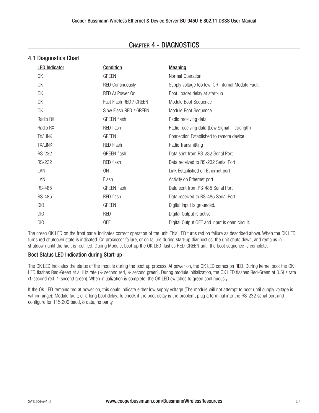
LED Indicator | Condition | Meaning |
OK | GREEN | Normal Operation |
OK | RED Continuously | Supply voltage too low. OR Internal Module Fault |
OK | RED At Power On | Boot Loader delay at |
OK | Fast Flash RED / GREEN | Module Boot Sequence |
OK | Slow Flash RED / GREEN | Module Boot Sequence |
Radio RX | GREEN flash | Radio receiving data |
Radio RX | RED flash | Radio receiving data (Low Signal strength) |
TX/LINK | GREEN | Connection Established to remote device |
TX/LINK | RED Flash | Radio Transmitting |
GREEN flash | Data sent from | |
RED flash | Data received to | |
LAN | ON | Link Established on Ethernet port |
LAN | Flash | Activity on Ethernet port. |
GREEN flash | Data sent from | |
RED flash | Data received to | |
DIO | GREEN | Digital Input is grounded. |
DIO | RED | Digital Output is active |
DIO | OFF | Digital Output OFF and Input is open circuit. |
The green OK LED on the front panel indicates correct operation of the unit. This LED turns red on failure as described above. When the OK LED turns red shutdown state is indicated. On processor failure, or on failure during
Boot Status LED Indication during Start-up
The OK LED indicates the status of the module during the boot up process. At power on, the OK LED comes on RED. During kernel boot the OK LED flashes
If the OK LED remains red at power on, this could indicate either low supply voltage (The module will not attempt to boot until supply voltage is within range); Module fault; or a long boot delay. To check if the boot delay is the problem, plug a terminal into the
3A1582Rev1.6 | www.cooperbussmann.com/BussmannWirelessResources | 57 |


