Cooper Bussmann BU-945U-E 802.11 DSSS user manual Client 1 Configuration, Client 2 Configuration

Page 55

Cooper Bussmann Wireless Ethernet & Device Server BU-945U-E 802.11 DSSS User Manual

Client 1 Configuration

Perform the same configuration steps as the Access Point configuration with the following differences:

Set the Ethernet and Wireless IP addresses of BU-945U-E to 192.168.0.201

Set the Operating Mode to Client.

Ensure the ESSID and Radio Encryption method match the Access Point.

If encryption is used, ensure the encryption keys or passphrase match the Access Point.

Client 2 Configuration

• As above, however set the Ethernet and Wireless IP addresses as 192.168.0.202

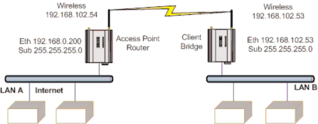
Connecting Two Separate Networks Together

LAN A Configuration

In this example, network A is connected to the internet via a router at IP address 192.168.0.1.

Devices on LAN A that only require access to devices on LAN A and B, should have their gateway IP address set to the BU-945U-E Access Point as 192.168.0.200.

Devices on LAN A, that must interact with devices on LAN A and B and the internet should set the internet router 192.168.0.1 as their gateway, and must have a routing rule established for devices on Network B. On PCs, this may be achieved with the MS-DOS command ROUTE. For this example use: ROUTE ADD 169.254.102.0 MASK 255.255.255.0 192.168.0.200. For more information on the DOS “Route” command see section 4.3 “Utilities”

LAN B Configuration

All devices on LAN B should be configured so their gateway IP address is that of the BU-945U-E Access Point as 169.254.102.54

3A1582Rev1.6

www.cooperbussmann.com/BussmannWirelessResources

55

Image 55
Contents Read Retain FCC Notice Cooper Bussmann Application EngineeringPhone 800 a.m 500 p.m. Central, M-F 636 Fax 636 GNU Free Documentation License Important NoticeCooper Bussmann Contents Access Point vs Client BU-945U-E 802.11 630mW max powerNetwork Topology 3A1582Rev1.6 Bridge vs. Router Getting Started Quickly General Antenna InstallationAntennas Bench test and Demo System SetupPlant and Factory Installations Line-of-sight installationsOmni-directional Antennas Installation tipsRS232 Serial Port Power SupplySerial Connections Directional AntennasRS485 Serial Port DB9 Connector Pinouts3A1582Rev1.6 Discrete Digital Input/Output Start-up LED Indication Selecting a Channel802.11 900 MHz Channels 3A1582Rev1.6 Data Throughput Based on Repeater Hops Radio ThroughputDefault Configuration Configuring the Unit for the First TimeAccessing Configuration for the First Time For local addresses Power up the BU-945U-E moduleEnter the username user and default password user Method 1 Set PC to same network as BU-945U-E3A1582Rev1.6 Quick Start Quick Start ConfigurationNetwork Configuration Save Changes and Reset Dhcp Server Configuration, Default is uncheckedWireless ports will have the same IP address Configured Essid of the clientEncryption keys must not be all zeros, i.e Security Menu3A1582Rev1.6 Router Operation Radio ConfigurationNormal Operation Transparent Bridge OperationAccess point Bands Default is AutoSignal quality, etc Drop back to non-bursting modeChannel Selection Dhcp Client ConfigurationRadio Mode BU-945U-E Only Supports the 802.11 Standard Default distance is 20kmDNS Server Configuration Dhcp Server ConfigurationSpanning Tree Algorithm / Redundancy Multiple AP Repeater Mesh Network 3A1582Rev1.6 Site B WDS Configuration Example Extending range using WDSExample Adding Redundancy Example Roaming with WDS Access Points3A1582Rev1.6 Example WDS Routed Network Mouse, to highlight the entire row WDS Connections Routing RulesSTP Specifies a destination host Wireless Message FilteringInformation at a later time 3A1582Rev1.6 IP Address Filter Configuration MAC Address Filter ConfigurationUtilize the radio link. All other devices are blocked ARP Filter Configuration RS-232 PPP Server Serial Port ConfigurationSerial Gateway Modbus Modbus RTU to TCP Serial Gateway Server/Client/MulticastSerial Menu Modbus TCP to RTU GatewayMulticast Pipe Manager To be the same on all communicating Multicast devices Digital Input/OutputPort on the Client, i.e., Scada, DCS, etc Multicast Group IP AddressModbus I/O Transfer 3A1582Rev1.6 Modbus TCP Configuration on I/O Transfer Menu Modbus TCP Client Mappings on I/O Transfer Menu Module Information Configuration Module Information Webpage Fields System Tools Remote ConfigurationSetting a BU-945U-E to Factory Default Settings Configuration ExamplesExtending a Wired Network Client 2 Configuration Client 1 ConfigurationLAN B Configuration Client Configuration Access Point ConfigurationExtending Range of a Network with a Repeater Hop RED Continuously Diagnostics ChartBoot Status LED Indication during Start-up LED Indicator Condition MeaningSite Survey Diagnostic Information AvailableConnectivity Connectivity ParametersNetwork Traffic Analysis Statistics5014 STA Only Internal Diagnostic Modbus Registers9999 Both Reset module enter Ffff to reset module Connection InformationStatistic Registers Utilities Testing Radio PathsPing 3A1582Rev1.6 Arp IpconfigRoute Serial Ports Power SupplyGeneral Radio TransceiverInput / Output status System ParametersAppendix a Firmware Upgrades Web-Based UpgradeDhcp ACKCSMA/CA CSMA/CDIPX-SPX IeeeISN SSL SNRNAT NICWEP VoIPVPN WANDBm to mW Conversion Materials InstallationIperf Applications 3A1582Rev1.6 JPerf Application 3A1582Rev1.6 Terms and Conditions Preamble3A1582Rev1.6 No Warranty 3A1582Rev1.6 Customer Assistance