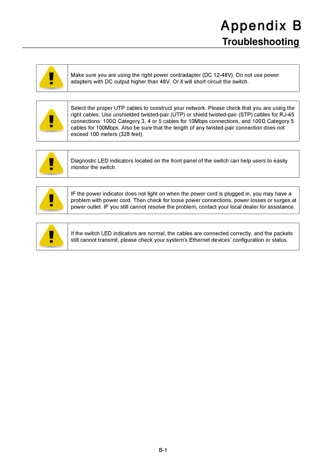
Husky HME-421E, HME-423E user manual Appendix B, Troubleshooting

Page 62

Appendix B

Troubleshooting

Make sure you are using the right power cord/adapter (DC 12-48V). Do not use power adapters with DC output higher than 48V. Or it will short circuit the switch.

Select the proper UTP cables to construct your network. Please check that you are using the right cables. Use unshielded twisted-pair (UTP) or shield twisted-pair (STP) cables for RJ-45 connections: 100Ω Category 3, 4 or 5 cables for 10Mbps connections, and 100Ω Category 5 cables for 100Mbps. Also be sure that the length of any twisted-pair connection does not exceed 100 meters (328 feet).

Diagnostic LED indicators located on the front panel of the switch can help users to easily monitor the switch.

IF the power indicator does not light on when the power cord is plugged in, you may have a problem with power cord. Then check for loose power connections, power losses or surges at power outlet. IF you still cannot resolve the problem, contact your local dealer for assistance.

If the switch LED indicators are normal, the cables are connected correctly, and the packets still cannot transmit, please check your system’s Ethernet devices’ configuration or status.
B-1

Image 62
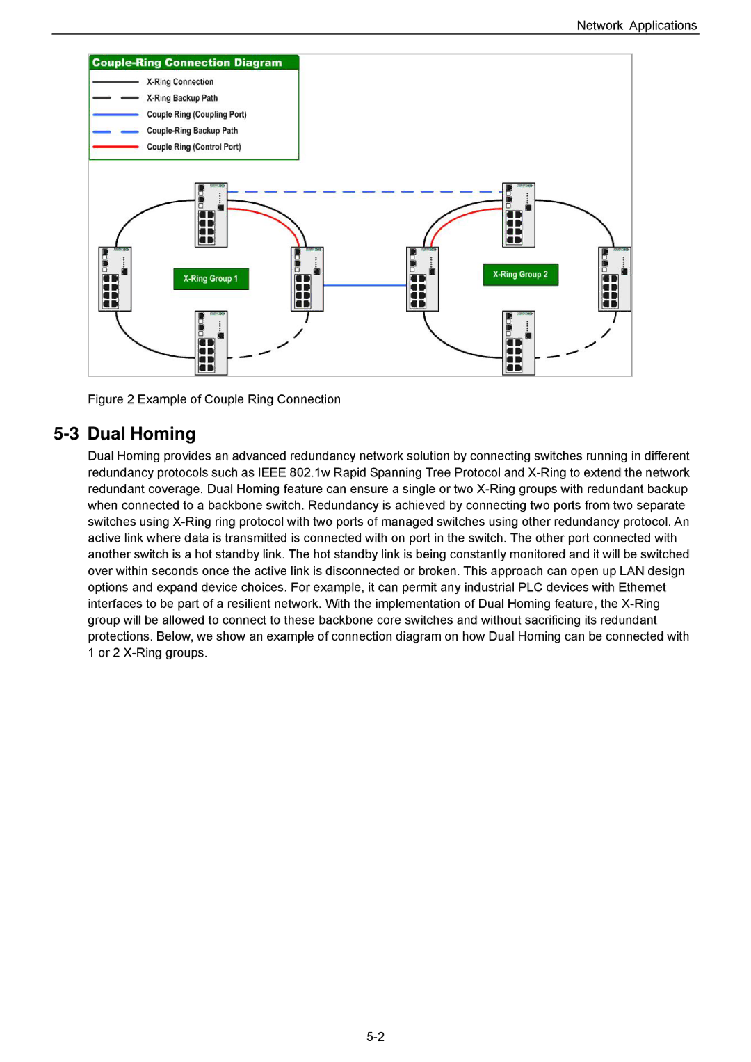
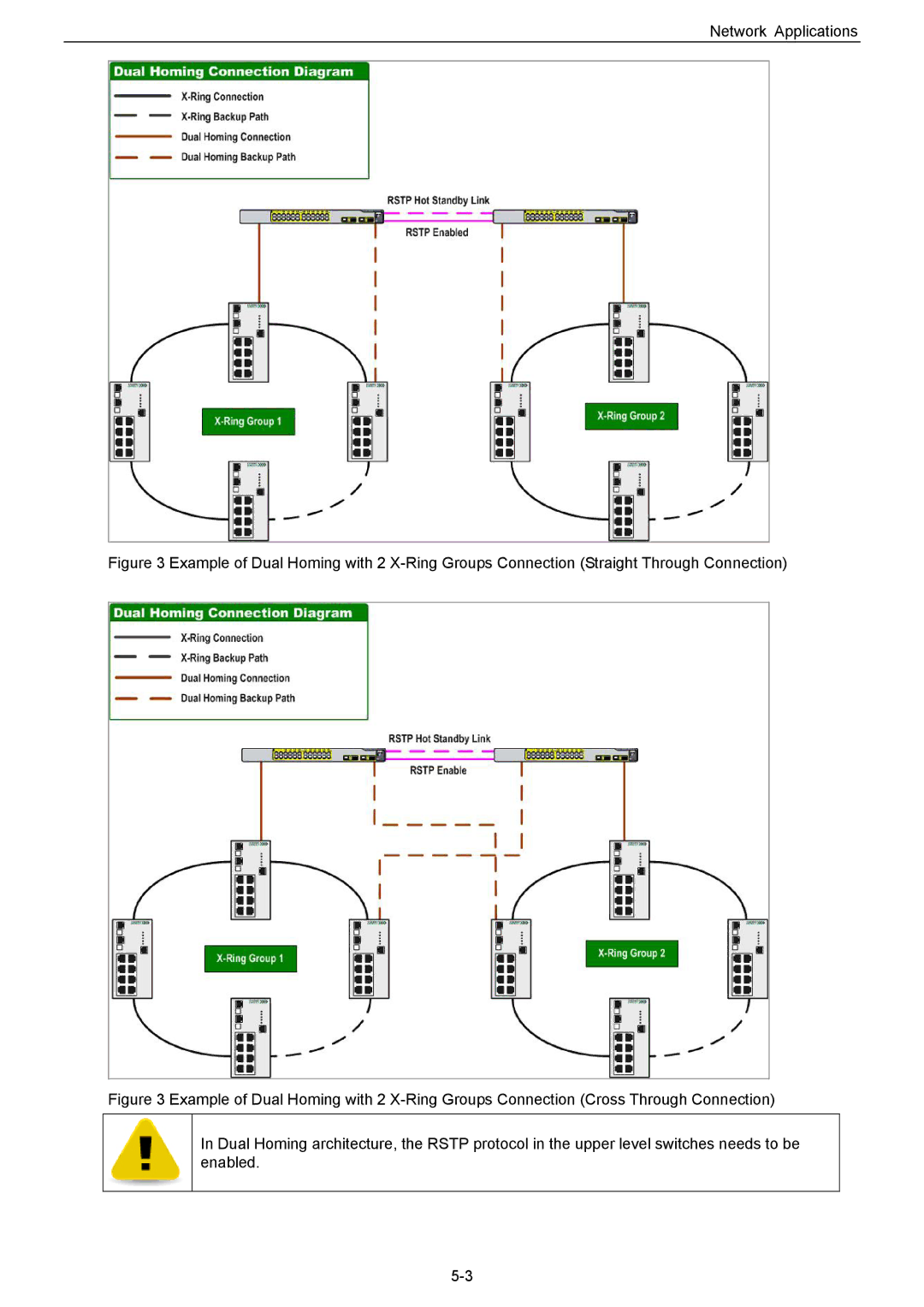
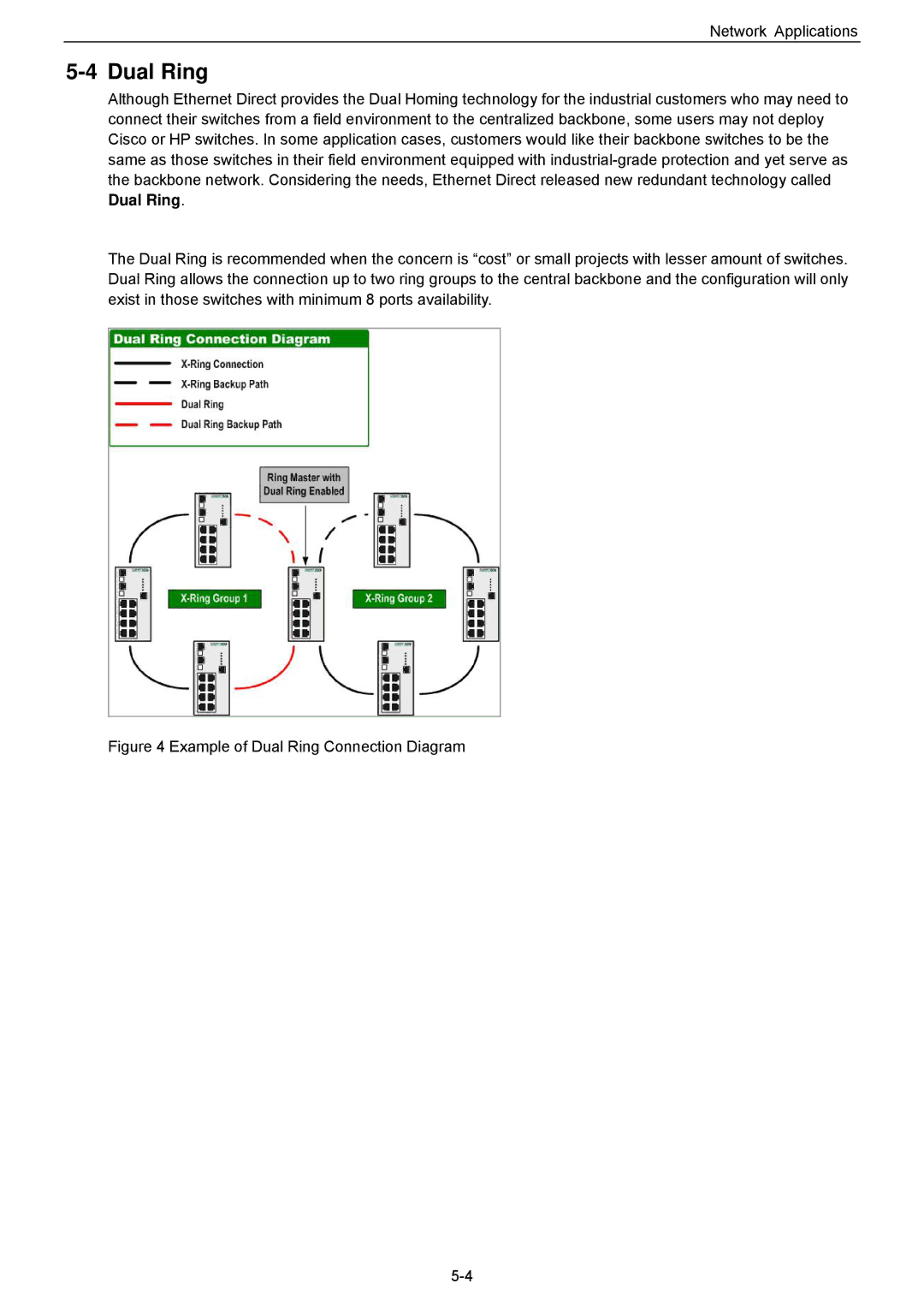
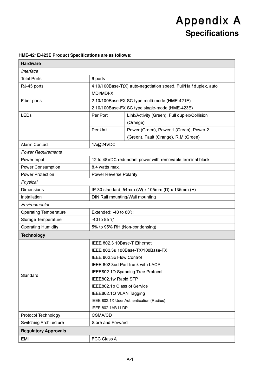
Contents HME-421E/423E Copyright Notice Table of Contents Ring Application Couple Ring Dual Homing Dual Ring Page Overview Product FeaturesIntroduction Package Checklist Front Panel Side Panel Hardware InstallationDimensions and Panel Layout Back Panel Bottom PanelLED Name LED Color LED Function LED IndicatorsRJ-45 Ports 1 RJ-45 Pin AssignmentsFiber Ports PinDIN-Rail Mounting Installing Your Ethernet Direct SwitchMounting The Switch Wiring The Power Inputs Wall MountingWiring The Fault Alarm Contact CablingPage Login The Console Interface Configuration Using Console InterfaceConnecting Console Port CLI ManagementConfigure Command LevelsModes Access Method Prompt Exit Method About This Mode DatabaseAbout Web-based Management Interface Configuration Using a Web BrowserSystem Login Preparing for Web-based ManagementBasic Settings Management Main ScreenPort Statistics User AuthenticationConfirm password PortIP Configuration Fault Relay AlarmPower Failure Port Link Down/BrokenUpdating Firmware by Tftp Restoring Configurations by TftpBacking up Configurations by Tftp Advanced Management Settings Security SpeedDuplex Rate LimitingSource Port Port MirroringDestination Port Dhcp ServerLease Time sec Low IP AddressHigh IP Address Port and IP Bindings by Dhcp ServerSystem Log Server IP System Event Log Syslog ConfigurationSyslog Client Mode AddressEmail Alert Smtp ConfigurationAuthentication Smtp Server IPPort event selection Event ConfigurationSystem event selection Daylight Saving Time Sntp ConfigurationSntp Client UTC TimezoneEnable Http Server Mins Switch TimerIP Security Mode Enable Telnet ServerSystem Priority Aggregator SettingsPort Trunking Group IDGroup Key Lacp DisabledAggregator Information Port MemberLacp Enabled State Activity Vlan Configuration Port-based VlanPage Ieee 802.1Q Tag-based Vlan 11.2.1 802.1Q Configuration Vlan Operation ModeEnable Gvrp Management Vlan IDTagged VID Link TypeUntagged VID Group Configuration QoS Policy QoS ConfigurationUse an 8, 4, 2, 1 weighted fair queuing scheme Use the strict priority schemeIgmp Configuration Leave Group Snmp ConfigurationAgent Mode Community StringsCommunity Trap ConfigurationSnmp v3 Configuration Trap VersionContext Table Context Name Group Table Security Name User IDContext Match Rule Access Table Context PrefixSecurity Level Read View NameLldp Interval Lldp ConfigurationLldp Protocol Rstp Mode Rapid Spanning Tree Protocol Configuration RstpSystem Configuration Forward Delay TimeAdmin Non Stp Admin P2PAdmin Edge Ring ConfigurationEnable Dual Homing Enable RingEnable Couple Ring Enable Dual RingRadius Server IP 18 802.1X/Radius ConfigurationIeee 802.1x Protocol Server PortReject DisableMisc Configuration AcceptStatic MAC Address Settings Supplicant TimeoutServer Timeout Max RequestsMAC Filtering All MAC AddressesMulticast Filtering Member PortsCouple Ring Network ApplicationsRing Application Dual Homing Example of Couple Ring ConnectionNetwork Applications Example of Dual Ring Connection Diagram Dual RingRegulatory Approvals SpecificationsTechnology Management Specifications Dhcp Troubleshooting Appendix BSystem Commands Set Command Set ListsCommands Set List Port Commands Set Broadcast-only Broadcast-multicast-flooded-unicastBroadcast-multicast Trunk Commands Set Vlan Commands SetSwitchvlan#vlanmode 802.1q Switch#vlan databaseSwitchvlan#vlanmode portbase Ported based Vlan configurationSpanning Tree Commands Set QoS Commands Set Igmp Commands SetMac / Filter Table Commands Set Snmp Commands SetGroup G1 password AuthPW PrivPW Switchconfig#snmpv3 context-nameSwitchconfig#snmpv3 user test01 Switchconfig#snmpv3 mibview viewPort Mirroring Commands Set 12 802.1x Commands SetTftp Commands Set SystemLog, Smtp and Event Commands Set Sntp Commands Set Ring Commands SetSwitchconfig# no ring couplering Switchconfig#ring homingportSwitch#show ring Switchconfig# no ring dualhoming