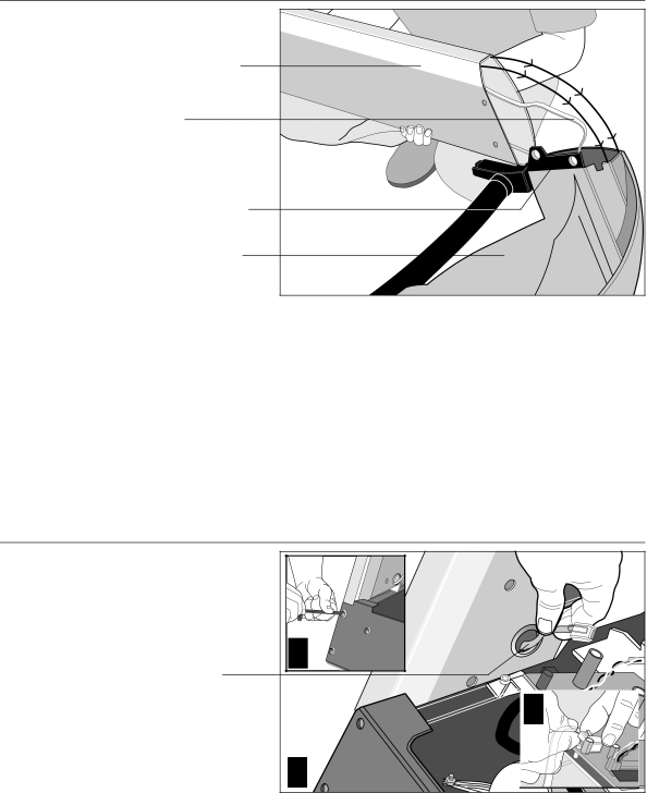
Precor M9.55 owner manual Console

Page 13

Diagram 5

Attach the display


console.


Upright support


Cable


Right side support


Display console


(bottom side)

a.Make sure that the cable is routed through the hole in the upright support.

b.Place a protective base (cardboard or plastic sheeting from the shipping container) on the floor. Position the display console (display-side down) onto it.

c.Remove 2 screws (A) and washers (B) from the hardware kit.

d.Align the upright support mounts with the display console’s. Insert 2 screws and washers. Tighten the screws securely with the hex key provided.

9.Attach the display console assembly to the base. Diagram 6. Take the following steps to install the display console assembly onto the treadmill.

a.Position the display console and right upright support over the column support mount located on the base.

Diagram 6

Connect the cable and attach the right side support to the base.

Route cable through hole.

2

3

1

CAUTION: Do not crimp or pinch the cable! Crimped or pinched cables are not covered by the Precor limited warranty.

b.Carefully lower the upright support and align the mounting holes. See Diagram 6 #2. Check that the display console is seated properly on the left upright support. Insert 5 screws (A) with washers (B). Thread the screws into the unit, but leave them loose for final adjustments. Do not securely tighten the screws until after the display console and handrails have been installed.

c.Plug the connector into its receptacle on the lower board. A definite “click” is heard when the cable is properly attached. See Diagram 6 #3. If you do not hear and feel the connector “snap” into place, reinsert it.

page 13

Image 13
Contents Low Impact Treadmill Important Safety Instructions Precor Heart Rate Option-Safety Guide- lines Personal SafetyEuropean Applications RFI Radio Frequency InterferenceEuropean Applications 240 Volt Units Only Grounding Instructions Safety ApprovalTable of Contents Using the Polar Equipment Page Before You Begin Obtaining ServiceUnpacking the M9.55 Low Impact Treadmill Optional EquipmentHardware Kit DiagramAcquiring the Appropriate Tools Installation Requirements Setting Up the TreadmillAssembly Instructions Diagram Console Console Handrail bracket Secure Hood Foot Turning the Unit on and OFFIf the running belt Then Checking the Alignment of the Running BeltSafety Features Using the M9.55 TreadmillUsing the Security Clip Entering a PasswordSmart Rate Heart rate display Workout TipsDisplay and data entry fields Change keysQuick Steps to Working Out Continue your workout End your workout Cooling Down After Your WorkoutPause, Cool Down, Workout Summary, and Exit Features Using the Quick Start FeatureStop ResetSpeed M9.55 Display Features on the Display ConsoleChanging the User Display Fields Upper DisplayDeleting Workout Statistics WeightUpper Display Smart Rate DisplayLower Display Keys on the Display Console Keypad Tips Prompts Default Value Quick Start Default ValuesSelecting a U.S. Standard or Metric Display Programming the M9.55 TreadmillRed Stop button, 5, 6, 7 Creating a User Name Securing the Treadmill with a PasswordSpeed , Speed M9.55 Courses Course Features and Course DescriptionsType of course Description Manual Track Miracle Mile Yellow Brick Road Urban ParkRandom Course Utilizing the Heart Rate Interactive Capabilities Utilizing the Smart Rate FeatureHeart Rate Course Wearing the Polar Chest Strap Using the Polar EquipmentStoring the Polar Chest Strap Maintaining the Treadmill Cleaning the EquipmentAligning the Running Belt Long Term Storage Servicing the TreadmillExploded View Exploded ViewsExploded Views Exploded Views Exploded Views Exploded Views Exploded Views Exploded Views Elliptical Fitness Crosstrainers and Motorized Treadmills Residential Equipment Limited WarrantyStretchTrainer Fill this portion out and keep for your recordsElectronic Specifications Product SpecificationsM9.55 Programs C955 Display Readouts