


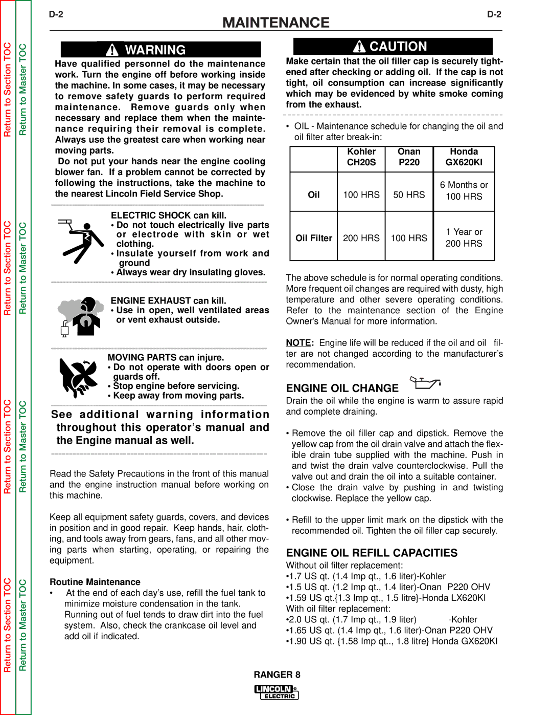
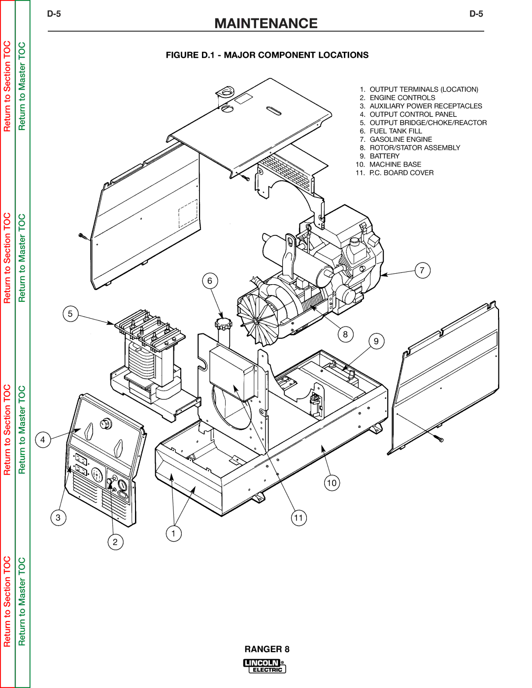


Return to Section TOC
Return to Section TOC
Return to Master TOC
Return to Master TOC
|
|
| |||
| INSTALLATION |
| |||
| Connection of the | Welder Operation |
| ||
| • Shut the welder off. | Welder Output |
| ||
|
|
| |||
| • Connect the | • | Maximum Open Circuit Voltage at 3700 RPM is | ||
| instructions on the connection diagram S17742 | ||||
| (can be found in the back of this manual). |
| 80 Volts RMS. |
| |
| • Place the “RANGE” switch to the “WIRE FEED” | • | Duty Cycle: 100% for both welding and auxiliary | ||
| position and the “POLARITY” switch to the |
| power. |
| |
| desired polarity. |
|
|
|
|
|
|
|
| Ranger 8 | |
|
|
|
|
| |
| • Place the “IDLER” switch in the “HIGH” idle |
|
|
|
|
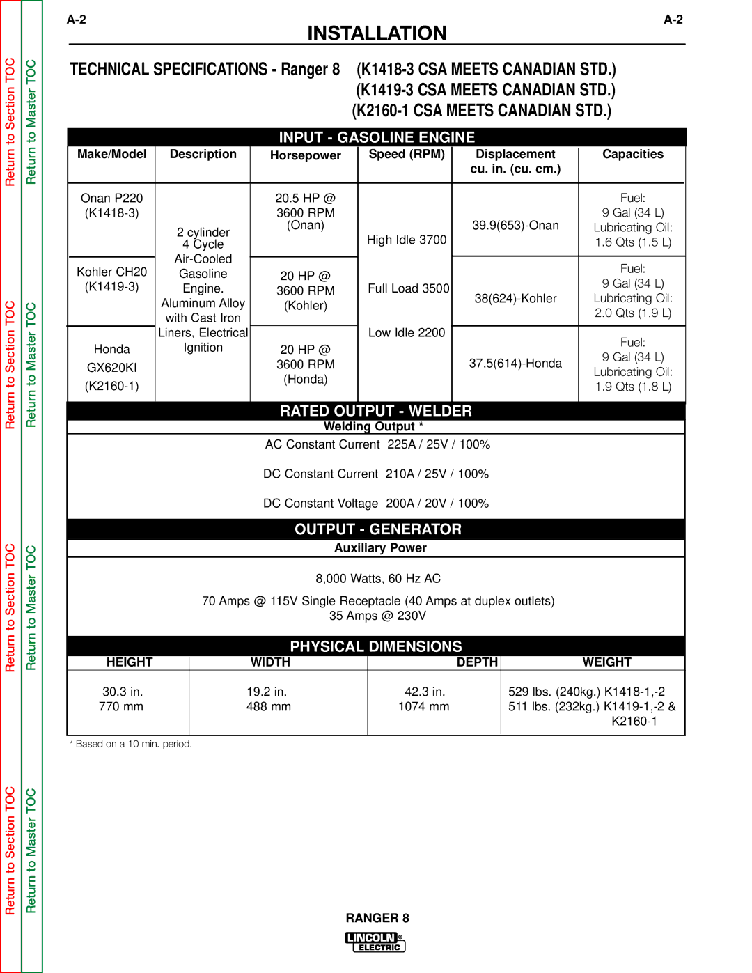
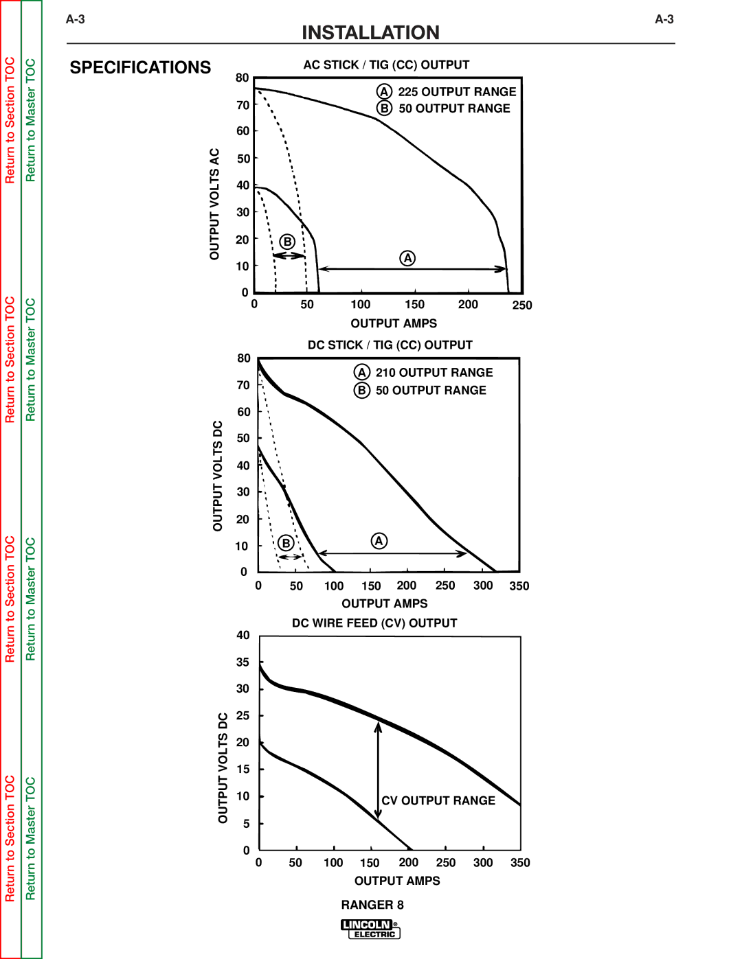
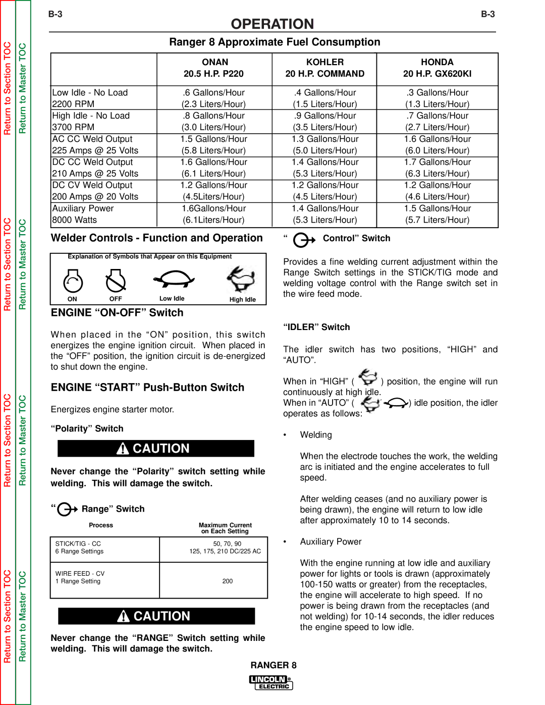
| Constant Current |
| 225 Amps AC @ 25 Volts | ||
| position. The engine idling device may not |
| |||
|
|
|
| 210 Amps DC @ 25 Volts | |
| function when welding in the “WIRE FEED” mode. |
|
|
| |
|
|
|
|
| |
| • Adjust wire feed speed at the | Constant Voltage |
| 200 Amps DC @ 20 Volts | |
|
|
|
|
| |
| welding voltage with the output “CONTROL” at |
|
|
|
|
|
|
|
|
| |
| the welder. | Auxiliary Power |
| ||
| NOTE: If the output “CONTROL” is set below “3” the |
|
|
|
|
| K240 contactor may not pull in. | The Ranger 8 can provide up to 8,000 watts of 115/230 | |||
|
| ||||
| Connection of | volts AC, single phase 60Hz power for continuous use. | |||
| The front of the machine includes three receptacles for | ||||
| Ranger 8. | connecting the AC power plugs; one 50 amp 115/230 | |||
|
| volt NEMA | |||
| The TIG Module is an accessory that provides high | NEMA | |||
| frequency and shielding gas control for AC and DC |
|
|
|
|
| GTAW (TIG) welding. See IM528 supplied with the |
|
|
|
|
| TIG Module for installation instructions. |
|
|
|
|
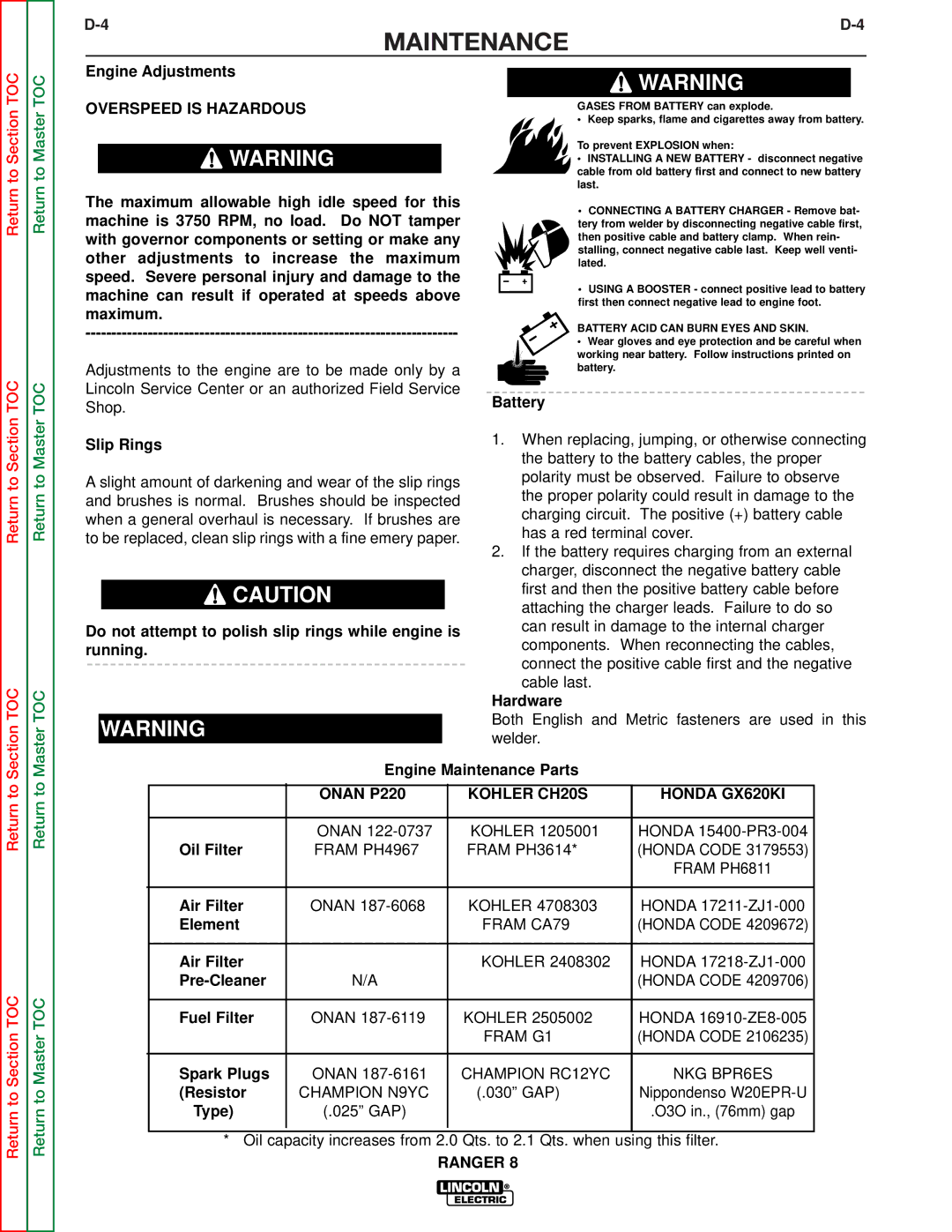
Return to Section TOC
Return to Section TOC
Return to Master TOC
Return to Master TOC
Note: The TIG Module does not require the use of a high frequency bypass capacitor. However, if the Ranger 8 is used with any other high frequency equip- ment, the bypass capacitor must be installed - order kit T12246.
INSTRUCTIONS
Additional Safety Precautions
Always operate the welder with the roof and case sides in place as this provides maximum protection from moving parts and assures proper cooling air flow.
Read and understand all Safety Precautions before operating this machine. Always follow these and any other safety procedures included in this manual and in the Engine Owner’s Manual.
![]() CAUTION
CAUTION
Do not connect any plugs that connect to the power receptacles in parallel.
Start the engine and set the “IDLER” control switch to the desired operating mode. Set the “CONTROL” to
10.Voltage is now correct at the receptacles for auxil- iary power.
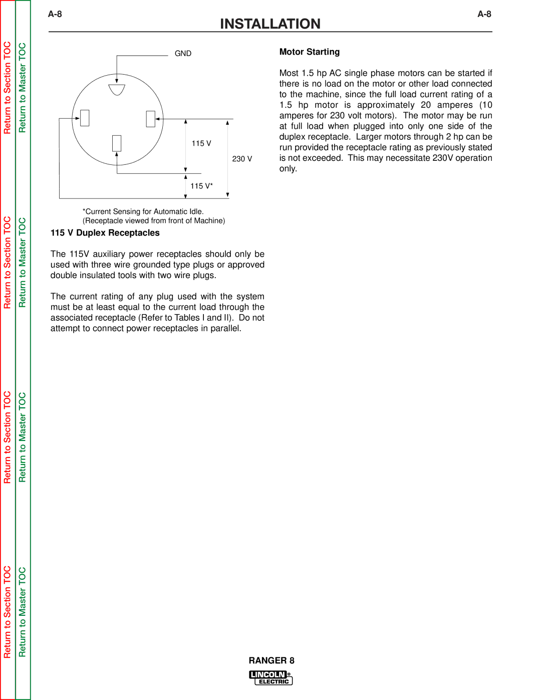
115/230 Volt Dual Voltage Receptacle
The 115/230 volt receptacle can supply up to 40 amps of 230 volt power to a two wire circuit, up to 40 amps of 115 volts power from each side of a three wire cir- cuit (up to 70 amps total). Do not connect the 115 volt circuits in parallel. Current sensing for the automatic idle feature is only in one leg of the three wire circuit as shown in the following column.
RANGER 8