Lincoln Electric SVM107-B Engine OIL Change, Engine OIL Refill Capacities, Routine Maintenance

Page 30

D-2

D-2


MAINTENANCE

Return to Section TOC

Return to Section TOC

Return to Section TOC

Return to Section TOC

Return to Master TOC

Return to Master TOC

Return to Master TOC

Return to Master TOC

WARNING

Have qualified personnel do the maintenance work. Turn the engine off before working inside the machine. In some cases, it may be necessary to remove safety guards to perform required maintenance. Remove guards only when necessary and replace them when the mainte- nance requiring their removal is complete. Always use the greatest care when working near moving parts.

Do not put your hands near the engine cooling blower fan. If a problem cannot be corrected by following the instructions, take the machine to the nearest Lincoln Field Service Shop.

-----------------------------------------------------------------------

ELECTRIC SHOCK can kill.

• Do not touch electrically live parts or electrode with skin or wet clothing.

Insulate yourself from work and ground

Always wear dry insulating gloves.

------------------------------------------------------------------------

ENGINE EXHAUST can kill.

• Use in open, well ventilated areas or vent exhaust outside.

------------------------------------------------------------------------

MOVING PARTS can injure.

Do not operate with doors open or guards off.

• Stop engine before servicing.

Keep away from moving parts.

------------------------------------------------------------------------

See additional warning information throughout this operator’s manual and the Engine manual as well.

------------------------------------------------------------

Read the Safety Precautions in the front of this manual and the engine instruction manual before working on this machine.

Keep all equipment safety guards, covers, and devices in position and in good repair. Keep hands, hair, cloth- ing, and tools away from gears, fans, and all other mov- ing parts when starting, operating, or repairing the equipment.

Routine Maintenance

At the end of each day’s use, refill the fuel tank to minimize moisture condensation in the tank. Running out of fuel tends to draw dirt into the fuel system. Also, check the crankcase oil level and add oil if indicated.

CAUTION

Make certain that the oil filler cap is securely tight- ened after checking or adding oil. If the cap is not tight, oil consumption can increase significantly which may be evidenced by white smoke coming from the exhaust.
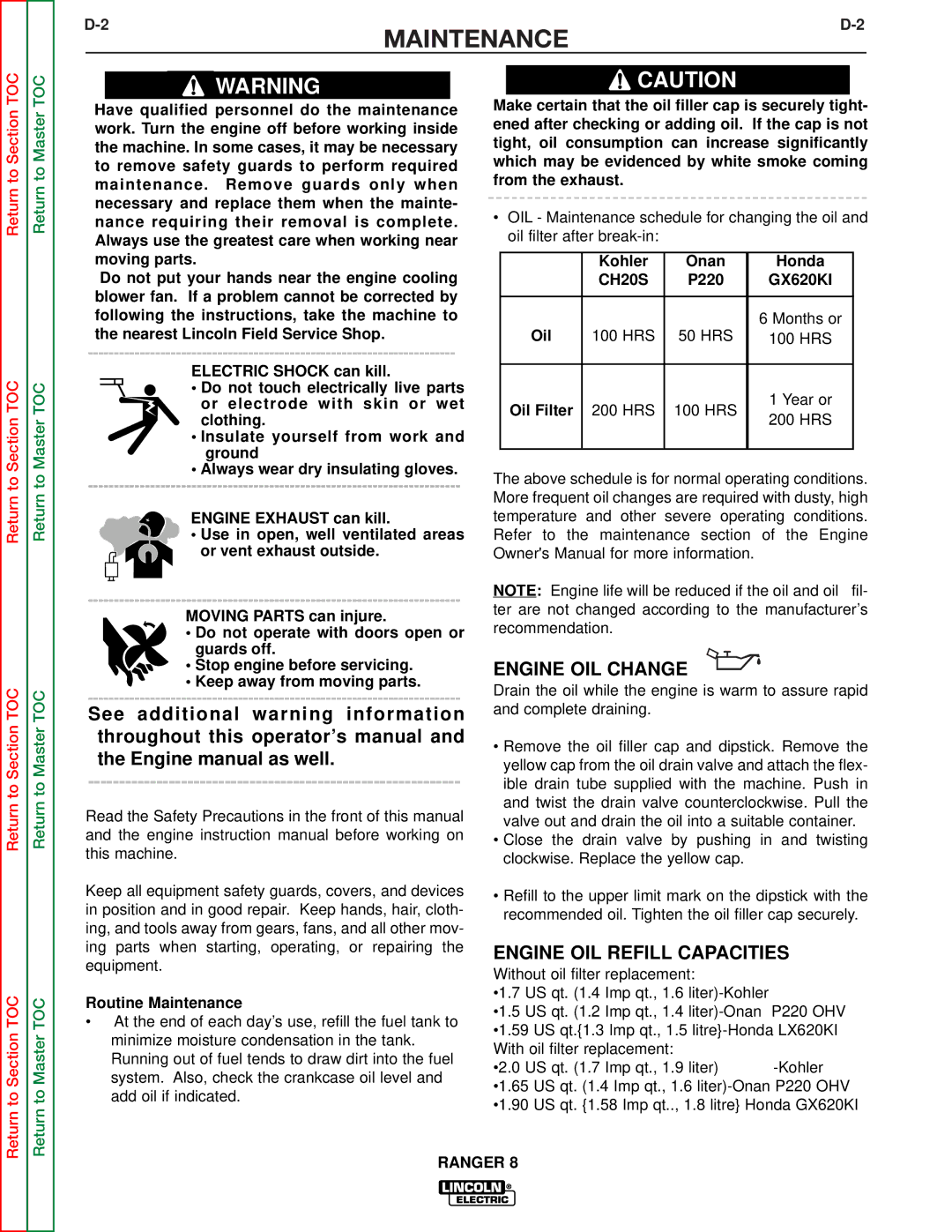
OIL - Maintenance schedule for changing the oil and oil filter after break-in:


Kohler

Onan

Honda


CH20S

P220

GX620KI


Oil

100 HRS

50 HRS

6 Months or

100 HRS


Oil Filter

200 HRS

100 HRS

1 Year or

200 HRS


The above schedule is for normal operating conditions. More frequent oil changes are required with dusty, high temperature and other severe operating conditions. Refer to the maintenance section of the Engine Owner's Manual for more information.

NOTE: Engine life will be reduced if the oil and oil fil- ter are not changed according to the manufacturer’s recommendation.

ENGINE OIL CHANGE

Drain the oil while the engine is warm to assure rapid and complete draining.

Remove the oil filler cap and dipstick. Remove the yellow cap from the oil drain valve and attach the flex- ible drain tube supplied with the machine. Push in and twist the drain valve counterclockwise. Pull the valve out and drain the oil into a suitable container.

Close the drain valve by pushing in and twisting clockwise. Replace the yellow cap.

Refill to the upper limit mark on the dipstick with the recommended oil. Tighten the oil filler cap securely.

ENGINE OIL REFILL CAPACITIES

Without oil filter replacement:

•1.7 US qt. (1.4 Imp qt., 1.6 liter)-Kohler

•1.5 US qt. (1.2 Imp qt., 1.4 liter)-Onan P220 OHV •1.59 US qt.{1.3 Imp qt., 1.5 litre}-Honda LX620KI With oil filter replacement:

•2.0 US qt. (1.7 Imp qt., 1.9 liter) -Kohler •1.65 US qt. (1.4 Imp qt., 1.6 liter)-Onan P220 OHV •1.90 US qt. {1.58 Imp qt.., 1.8 litre} Honda GX620KI

RANGER 8

Image 30
Contents Rangertm Safety Electric Shock can kill Welding Sparks can cause fire or explosion IiiPrécautions DE Sûreté Master Table of Contents for ALL Sections Table of Contents Installation Section Auxiliary Power Welding Output20 B 50 100 150 20050 100 150 200 250 300 350 Output Amps Installation Instructions AWG Battery ConnectionsOil FuelAngle of Operation Ranger Connection of the LN-7 to the RangerWelder Output Constant CurrentDuplex Receptacles Motor StartingElectrical Device USE with the Ranger Type Common Electrical Devices Possible ConcernsAuxiliary Power While Welding Standby Power ConnectionsConnection of Ranger 8 to Premises Wiring Figure A.1Ranger Table of Contents Operation Section DC Semiautomatic Wire Feed Welding Constant Voltage AC/DC Stick Welding Constant CurrentAC/DC TIG Welding Constant Current Range Switch settings in the STICK/TIG mode Control SwitchProvides a fine welding current adjustment within Welding voltage control with the Range switch setStarting/Shutdown Instructions Stopping the EngineWire Feed Welding Processes Constant Voltage Stick Constant Current WeldingTIG Constant Current Welding Summary of Welding Processes Stick AutoSection C-1Section C-1 Accessories Recommended Equipment Ranger Table of Contents Maintenance Engine OIL Refill Capacities Routine MaintenanceEngine OIL Change Kohler Onan HondaOIL Filter Change Pre-Cleaner Engine AdjustmentsEngine Maintenance Parts Slip RingsFigure D.1 Major Component Locations Ranger Table of Contents Theory of Operation Section Theory of Operation Rotor Field Feedback and Auxiliary Power Weld WINDING, REACTOR, Range Switch Output BRIDGE, Choke Polarity SWITCH, and Output Terminals Ranger Table of Contents Trouble Shooting & Repair Section Troubleshooting & Repair HOW to USE Troubleshooting GuideDevices PC board can be damaged by static electricityStatic-Sensitive Handle only atTroubleshooting Guide Output ProblemsObserve Safety Guidelines Detailed in the beginning of this manualTroubleshooting & Repair Troubleshooting & Repair Troubleshooting Guide Troubleshooting & Repair Engine Problems Troubleshooting & Repair Troubleshooting & Repair Welding Problems Ranger Rotor Voltage Test Test DescriptionMaterials Needed Test Procedure Rotor Resistance Test Rotor Resistance Test Troubleshooting & Repair Ranger Auxiliary and Field Winding Test To test the 115 VAC winding To test the 230 VAC windingTo test the field winding Ranger Output Rectifier Bridge Test Output Rectifier Bridge Test Charging Circuit Test Charging Circuit Test Engine Throttle Adjustment Test Engine Throttle Adjustment Test Engine Throttle Adjustment Test Oscilloscope Method Scope Settings Normal Open Circuit Voltage Waveform 115 VAC SupplyHigh Idle no Load Output Control AT Maximum Typical DC Weld Output Waveform CV Mode Machine LoadedTypical DC Weld Output Waveform CC Mode Machine Loaded to 200 Amps AT 26 VDCTypical AC Weld Output Waveform Machine Loaded to 225 Amps AT 25 VDCAbnormal Open Circuit Weld Voltage Waveform CV Mode Abnormal Open Circuit DC Weld Voltage Waveform Normal Open Circuit Weld Voltage Waveform CV Mode Normal Open Circuit DC Weld Voltage Waveform CC Mode Normal Open Circuit AC Weld Voltage Waveform Ranger Brush Removal and Replacement DescriptionBrush Removal and Replacement ProcedureSlip Rings Figure F.10 Brush LEADS/BRUSHES Retained with Cable TIERanger Field Capacitor AND/OR Rectifier Bridge Removal Replacement Replacement Field Capacitor AND/OR Rectifier Bridge RemovalProcedure Rectifier Bridge Removal and Replacement Ranger Printed Circuit Board Removal Replacement Printed Circuit Board Removal and Replacement ProcedurePrinted Circuit Board Removal Ranger Output Rectifier Bridge Removal Replacement Remove the case top, then reinstall the fuel cap Output Rectifier Bridge RemovalSection TOC Ranger ENGINE/ROTOR Removal and Replacement InstructionsENGINE/ROTOR Removal Figure F.14 Component LOCATIONS, ENGINE/ROTOR RemovalEngine and Rotor Removal Procedure Rotor Removal Procedure Figure F.15 Engine and Rotor Removed from StatorReplacement KIT S20788 Reassembly ProcedureRetest After Repair Table of Contents Diagrams Section Dimension Dimension Print Ranger 8 Honda & Kohler RANGER8Diagrams Connection of Ranger 8 to LN-7 & K240 Contactor KITElectrical Diagrams Wiring Diagram Onan NON CSA ModelK1418-2 Ranger 8 Onan CSA Version Wiring Diagram Wiring Diagram Onan CSA ModelK1419-1 Ranger 8 Kohler Wiring Diagram Wiring Diagram Kohler NON CSA ModelK1419-2 Ranger 8 Kohler CSA Wiring Diagram Wiring Diagram Kohler CSA ModelK2160-1 Ranger 8 Honda CSA Wiring Diagram Schematic IDLER/CONTROL PC Board 16482PC Board Assembly IDLER/CONTROL SVM Error Reporting Form