


Return to Section TOC
Return to Section TOC
Return to Section TOC
Return to Section TOC
Return to Master TOC
Return to Master TOC
Return to Master TOC
Return to Master TOC
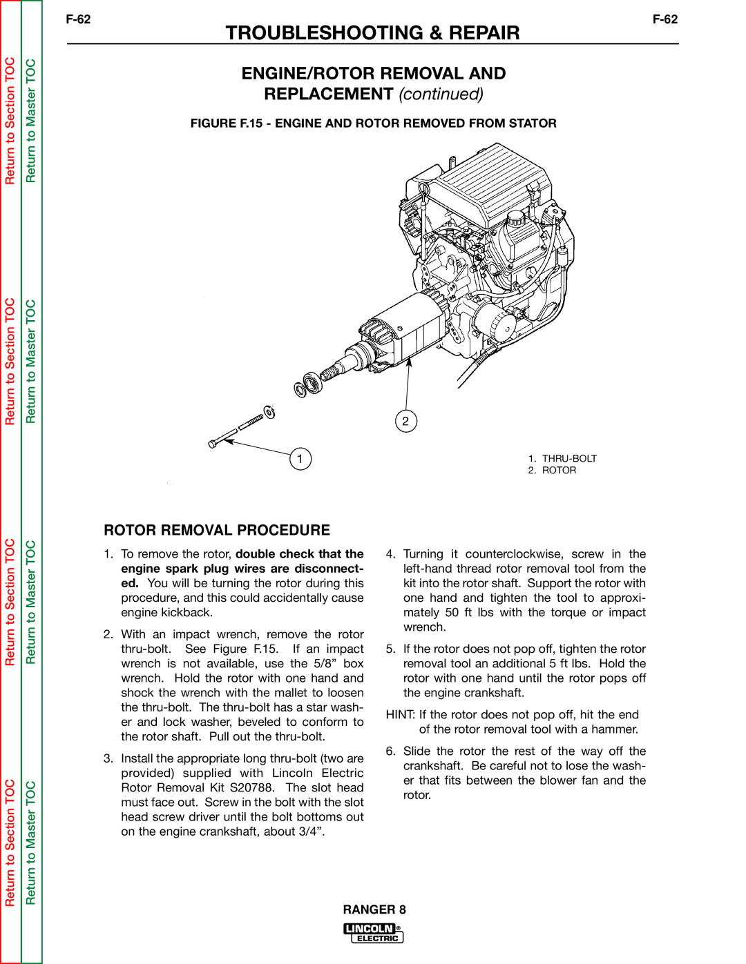
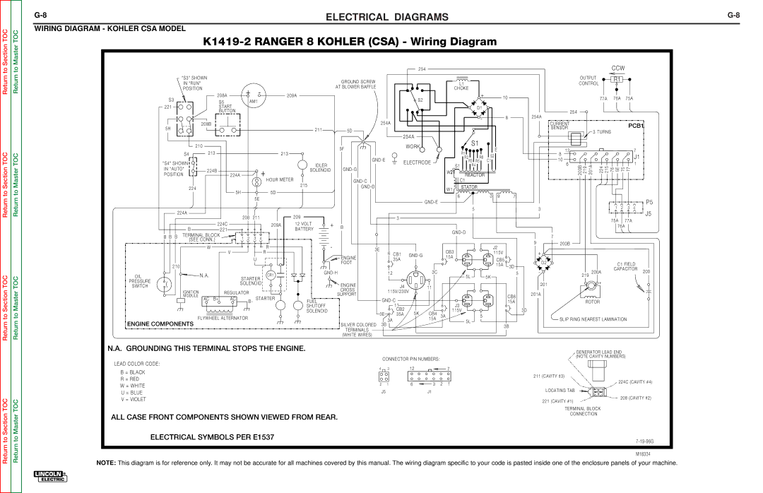
ELECTRICAL DIAGRAMS | ||
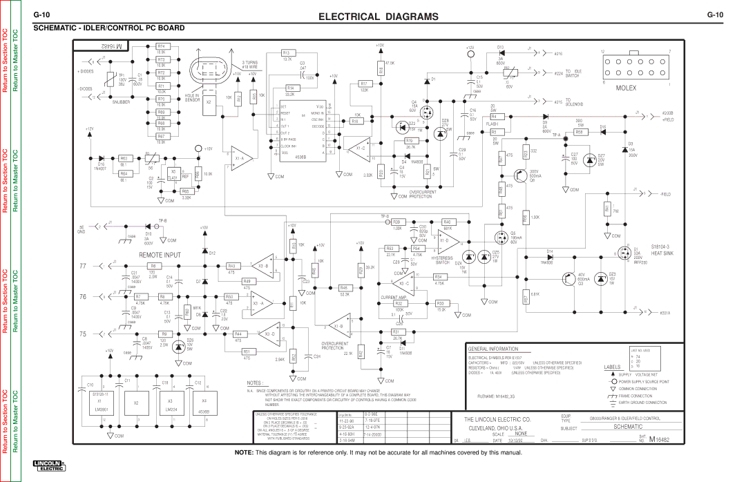
SCHEMATIC - IDLER/CONTROL PC BOARD |
|
|
| 16482 |
|
|
| R74 |
|
|
|
|
|
|
|
|
|
|
|
|
|
|
|
| +10V |
|
|
|
|
|
|
|
| +12V |
| D13 |
|
| J1 |
|
|
|
|
|
|
|
|
| |
|
|
|
|
|
|
|
|
|
|
|
|
|
|
|
|
|
|
|
|
|
|
|
|
|
|
|
|
|
|
|
|
|
|
|
| 12 |
|
|
| 7 | ||||||
|
|
|
|
|
| 10.0K |
|
|
|
|
|
|
| R13 |
|
|
|
|
|
|
|
|
|
|
|
|
|
|
|
|
|
|
|
|
|
| 4 | #216 |
|
|
|
|
|
| ||
| J1 |
|
|
|
|
|
|
|
|
|
|
|
|
|
|
|
|
|
|
|
|
|
|
|
|
|
|
|
|
|
|
|
|
|
|
|
|
|
|
|
|
|
|
| ||
|
|
|
|
| R73 |
|
|
|
|
|
|
| 13.7K |
|
|
|
|
|
|
|
|
|
|
|
|
|
|
|
|
|
| 3A |
|
|
|
|
|
|
|
|
|
|
|
| ||
6 |
|
|
|
|
|
|
|
| 3 TURNS |
|
| C3 |
|
|
|
|
|
| 47.5K |
|
|
|
|
|
|
|
|
|
|
|
|
|
|
|
|
|
|
|
| |||||||
|
|
|
|
| 10.0K |
|
|
|
|
|
|
|
|
|
|
|
|
|
|
|
|
|
|
|
|
| 600V |
|
|
|
|
|
|
|
|
|
|
| ||||||||
|
|
|
|
|
|
|
|
| #18 WIRE |
|
|
|
| .047 |
|
|
|
|
|
| R18 |
|
|
|
|
|
|
|
|
|
|
| R62 |
| J1 |
|
|
|
|
|
|
|
|
| ||
+ DIODES |
|
|
|
|
| R72 |
|
|
|
|
|
|
|
|
|
|
|
|
|
|
|
|
|
|
|
|
|
|
|
|
|
| TO | IDLE |
|
|
|
|
|
| ||||||
|
| TP1 | C1 |
|
|
|
| +10V | +10V |
|
|
|
|
|
|
| +10V |
|
|
|
|
|
|
|
|
|
|
|
|
|
|
|
| 9 | #224 |
|
|
|
|
|
| |||||
|
|
|
| 10.0K |
|
|
|
|
|
|
| 100V |
|
|
|
|
|
|
|
|
|
|
| D1 |
| C15 |
|
| + t |
|
| SWITCH |
|
|
|
|
|
| ||||||||
|
|
| 130V | .05 |
|
|
|
|
|
|
|
|
|
|
|
|
|
|
|
|
|
|
|
|
|
|
|
|
|
|
|
|
|
|
| 6 |
|
|
|
| ||||||
|
|
| 38J | 600V |
|
|
|
|
|
|
|
|
|
|
|
|
|
|
|
| R17 |
|
|
|
|
|
|
|
|
| 0.1 |
|
| .13 |
|
|
|
|
|
|
|
|
| 1 | ||
- DIODES |
|
|
| R71 |
|
|
|
|
|
|
| R14 |
|
|
|
|
|
|
|
|
|
|
|
|
|
| 50V |
|
| 60V |
|
|
|
|
|
|
| MOLEX | ||||||||
|
|
|
|
|
|
|
|
|
|
|
|
|
|
|
|
| 133K |
|
|
|
|
|
|
|
|
|
|
|
|
|
|
|
|
|
|
| ||||||||||
J1 |
|
|
|
| 10.0K |
|
|
|
|
|
|
|
|
|
|
|
|
|
|
|
|
|
|
|
|
| case |
|
|
|
|
|
|
|
|
|
|
| ||||||||
|
|
|
|
| HOLE IN |
|
| 15R | 10K | 33.2K |
|
|
|
|
|
|
|
|
|
|
|
|
|
|
|
|
|
|
|
| J1 |
|
|
|
|
|
|
|
|
| ||||||
12 |
|
|
|
| R70 |
| 10K |
|
|
|
|
|
|
|
|
|
|
|
|
|
|
|
|
|
|
|
|
|
|
|
|
|
|
|
|
|
| |||||||||
|
|
|
| SENSOR |
|
|
|
|
|
|
|
|
|
|
|
|
|
|
|
|
|
| D |
|
|
|
|
|
|
|
| TO |
|
|
|
|
|
|
| |||||||
|
| SNUBBER |
| X2 | 12R |
|
|
|
|
|
|
|
|
|
|
|
|
|
|
| Q4 |
|
|
|
|
|
|
|
| 3 | #215 |
|
|
|
|
|
|
| ||||||||
|
|
| 10.0K |
|
|
|
|
|
|
|
|
|
|
| 16 |
|
|
|
|
|
|
|
|
|
|
|
|
|
|
|
|
| SOLENOID |
|
|
|
|
|
| |||||||
|
|
|
|
|
|
|
|
|
|
|
| 1 | SET |
|
| V DD |
|
|
|
|
|
|
|
| 15A |
|
|
| C16 | 20 |
|
|
|
|
|
|
|
|
|
| ||||||
|
|
|
|
|
| R69 |
|
|
|
|
|
| 2 | RESET |
|
| MONO IN |
| 15 |
|
|
|
|
|
|
| 60V |
|
|
|
| 5W |
|
|
|
|
|
|
|
|
|
| J1 | #200B | ||
|
|
|
|
|
|
|
|
|
|
|
|
| X4 |
|
| 10K |
|
|
|
|
|
|
|
|
|
| 0.1 |
| R4 |
|
|
|
|
|
|
|
|
|
| |||||||
|
|
|
|
|
| 10.0K |
|
|
|
|
|
|
|
|
|
|
|
|
|
|
|
|
|
|
|
|
|
|
|
|
|
|
|
|
|
|
|
|
|
| 11 |
| ||||
|
|
|
|
|
|
|
|
|
|
|
| 3 | IN 1 |
|
| OSC INH |
| 14 | R16 |
|
|
|
|
|
| G |
| DZ8 |
| 50V |
|
|
|
|
|
| 390 |
|
|
|
| +FIELD | ||||
|
|
|
|
|
|
|
|
|
|
|
|
|
|
|
|
|
|
|
|
| S |
|
|
|
|
| D9 |
|
|
|
|
|
|
| ||||||||||||
|
|
|
|
|
| R68 |
|
|
|
|
|
|
|
|
|
|
|
|
|
|
|
|
|
| DZ2 |
|
| FLASH |
|
|
|
|
|
|
|
|
| |||||||||
+12V |
|
|
|
|
|
|
|
|
|
|
| 4 | OUT 1 |
|
| DECODE |
| 13 |
|
|
|
|
|
|
|
|
| 27V |
|
|
|
| 3A |
|
| 5W |
| D15 |
|
|
|
| ||||
|
|
|
|
| 10.0K |
|
|
|
|
|
|
|
|
|
|
|
|
|
|
|
|
|
| 15V | 1W | 5W |
|
|
|
|
|
|
|
|
|
|
|
|
|
| ||||||
|
|
|
|
|
|
|
|
|
|
| 5 | OUT 2 |
|
| D |
| 12 |
|
|
|
|
|
|
|
| case |
| R5 |
|
| 600V |
|
| R58 |
|
|
|
|
|
| ||||||
|
|
|
|
|
|
|
|
|
|
|
|
|
|
|
|
|
|
|
|
|
|
|
|
|
|
|
|
|
|
|
|
|
|
|
|
|
|
| ||||||||
|
|
|
|
|
| R67 |
|
|
|
|
|
| 6 |
|
|
|
|
| 11 |
|
|
|
|
|
|
|
|
|
|
|
|
|
| 20 |
|
|
|
|
|
|
|
|
|
| ||
|
|
|
|
|
|
|
|
|
|
|
| 8 |
| C |
|
|
|
|
|
|
|
| R19 |
|
|
|
|
|
|
|
|
|
|
|
|
|
|
|
|
|
| |||||
|
|
|
|
|
| 10.0K |
|
|
|
|
|
|
|
|
|
|
|
|
|
|
|
|
|
|
|
|
|
|
|
|
|
|
|
|
|
|
|
|
| |||||||
|
|
|
|
|
|
|
|
|
|
|
|
|
|
|
|
|
|
|
|
|
|
|
|
|
|
|
|
|
|
|
| 5W |
|
|
|
|
|
|
|
|
| D3 |
|
| ||
|
|
|
|
|
|
|
|
|
|
|
| 7 | CLOCK INH |
| B |
| 10 |
|
| 11 |
|
|
|
| 26.7K |
|
|
|
|
|
|
|
|
|
|
|
|
|
|
|
|
| ||||
|
|
|
|
|
|
|
|
| +10V |
|
|
|
|
|
|
|
|
|
|
|
|
|
|
|
|
|
|
|
|
|
|
|
|
|
|
|
|
|
| |||||||
|
|
|
|
|
|
|
|
|
|
|
| 8 | VSS |
|
| A |
| 9 | 13 | X1 |
|
|
|
|
|
|
|
| C29 |
|
|
| R23 | 332 |
|
|
|
|
|
| 15A |
| ||||
|
|
|
|
| R3 |
|
|
|
|
|
|
|
|
|
|
|
|
|
|
|
|
|
|
|
|
|
|
|
|
|
|
|
|
|
|
| ||||||||||
|
|
|
|
|
|
|
|
| 6 |
|
|
| 4536B |
|
|
|
|
|
|
|
|
|
|
|
|
|
| 0.1 |
| 47 | 475 |
|
|
| C27 |
| DZ7 |
| 200V |
| ||||||
|
|
| R63 |
|
|
|
|
|
|
|
|
|
|
|
|
|
| 10 |
|
|
|
|
|
|
|
|
|
|
|
|
|
|
|
| ||||||||||||
|
|
|
|
|
|
|
|
| X1 | 1 |
|
|
|
|
|
|
|
|
|
|
|
|
|
|
|
|
| 50V |
|
|
|
|
| 100 |
| 20V |
|
|
|
| ||||||
| D16 |
|
|
| + t |
|
|
|
|
|
|
|
|
|
|
|
|
|
|
|
|
|
| D4 | 1N4936 |
|
|
|
| R |
|
|
|
|
| 50V |
|
|
|
|
| |||||
|
| 68.1 |
| 1 |
|
|
|
|
|
|
|
|
|
|
|
|
|
|
|
|
|
|
|
|
|
|
|
|
|
|
|
|
| 5W |
|
|
|
| ||||||||
|
|
|
|
|
| 7 |
|
|
|
|
|
|
|
|
|
|
|
|
|
| C4 |
|
|
|
|
|
|
|
|
|
|
|
|
|
|
|
|
|
|
| ||||||
| 1N4007 |
|
|
| 56 |
|
|
|
|
|
|
|
|
|
|
|
|
|
|
|
|
|
|
|
|
| R21 | 5W |
|
|
|
|
|
|
|
|
|
|
|
|
|
|
|
| ||
|
|
|
| X5 | 8 |
|
|
|
|
|
|
|
|
|
|
|
|
|
|
| R20 |
|
|
|
|
|
|
|
|
|
| 300V |
|
|
|
|
|
|
|
|
| |||||
|
|
| R64 |
|
| R66 | 10.0K |
|
|
|
|
|
|
|
|
|
| COM |
| 3.32K |
| 18 |
|
|
| .5 |
|
|
|
|
|
|
|
|
|
|
|
|
|
|
| |||||
|
|
|
| C2 | TL431 | REF |
|
|
| COM |
|
|
|
|
|
|
| 15V |
|
|
|
|
|
|
|
|
| 500mA |
|
|
|
|
|
|
|
|
| |||||||||
|
|
| 68.1 |
|
|
|
|
|
|
|
|
|
|
|
|
|
|
|
|
|
|
|
|
|
|
|
|
|
|
|
|
|
|
| Q6 |
|
|
|
|
|
|
|
|
| ||
|
|
|
| 100 | 6 |
|
|
|
|
|
|
|
|
|
|
|
|
|
|
|
|
|
|
|
|
|
|
|
|
|
|
|
|
|
|
|
|
|
|
|
|
|
|
| ||
|
|
|
|
|
|
|
|
|
|
|
|
|
|
|
|
|
|
|
|
|
|
|
|
|
|
|
|
|
|
|
|
| 475 |
|
|
|
|
|
|
|
|
|
|
| ||
|
|
|
|
| 15V |
|
|
|
|
|
|
|
|
|
|
|
|
|
|
|
|
|
|
|
|
|
|
|
|
|
|
|
| 48R |
|
|
| COM |
|
|
| J1 |
| |||
|
|
|
|
|
| R65 |
|
|
|
|
|
|
|
|
|
|
|
|
|
|
|
|
|
|
|
|
|
|
|
|
|
|
|
|
|
|
|
|
|
| ||||||
|
|
|
|
|
|
|
|
|
|
|
|
|
|
|
|
|
|
|
|
|
|
|
|
|
| OVERCURRENT |
|
|
|
|
|
|
|
|
|
|
| |||||||||
|
|
|
|
|
|
|
|
|
|
|
|
|
|
|
|
|
|
|
|
|
|
|
|
|
|
|
|
|
|
|
|
|
|
|
|
|
|
| 5 | |||||||
|
|
|
|
|
|
| 3.32K |
|
|
|
|
|
|
|
|
|
|
|
|
|
|
|
|
| COM PROTECTION |
|
|
|
|
|
|
|
|
|
|
|
|
|
|
| ||||||
|
|
|
|
|
| COM |
|
|
|
|
|
|
|
|
|
|
|
|
|
|
|
|
|
|
|
|
|
|
|
|
|
|
|
|
|
|
|
|
| |||||||
|
|
|
|
|
|
|
|
|
|
|
|
|
|
|
|
|
|
|
|
|
|
|
|
|
|
|
|
|
|
|
|
|
|
|
|
|
|
|
|
|
|
|
|
|
| |
|
|
|
|
|
|
|
|
|
|
|
|
|
|
|
|
|
|
|
|
|
|
|
|
|
|
|
|
|
|
|
|
|
|
| 475 |
|
|
|
|
|
| R41 | .1 |
|
|
|
|
|
|
|
|
|
|
|
|
|
|
|
|
|
|
|
|
|
|
|
|
|
|
|
|
|
|
|
|
|
|
|
|
| 61 |
|
|
|
|
|
| 7W |
|
|
| ||
|
|
|
|
|
|
|
|
|
|
|
|
|
|
|
|
|
|
|
|
|
|
|
|
|
|
|
|
|
|
|
|
|
|
|
|
|
|
|
|
|
|
|
| |||
|
|
|
|
|
|
|
|
|
|
|
|
|
|
|
|
|
|
|
|
|
|
|
|
|
|
|
|
|
|
|
| R |
| 56 | 1.00K |
|
|
|
|
|
|
|
|
| ||
|
| J1 |
|
|
|
|
|
|
|
|
|
|
|
|
|
|
|
|
|
|
|
|
| R39 |
|
|
|
| R40 |
|
|
|
|
| R |
|
|
|
|
|
|
|
|
|
| |
|
|
|
|
|
|
|
|
|
|
|
|
| +10V |
|
|
|
|
|
|
|
|
|
|
|
| C30 |
|
|
|
|
|
|
|
|
|
|
|
|
|
|
|
| ||||
5E | 2 |
|
|
|
|
|
| +10V |
|
|
|
|
|
|
|
|
|
|
|
|
| 1.00K |
|
|
| 681K |
|
|
|
|
|
|
|
|
|
|
|
|
|
|
|
| ||||
|
|
|
|
|
|
|
|
|
|
|
|
|
|
|
|
|
|
|
|
|
|
|
|
|
|
|
|
|
|
|
|
|
|
|
|
|
|
|
| |||||||
GND |
|
|
|
| D10 |
|
|
|
|
|
|
|
|
|
|
|
|
|
|
|
|
|
|
|
|
|
|
| 820p |
|
|
|
|
| Q5 |
|
|
|
|
|
|
|
|
|
|
|
|
|
|
| case |
|
|
|
|
|
|
|
|
|
|
|
|
|
|
|
|
|
|
|
|
|
|
| 50V |
|
|
|
|
|
|
|
|
|
|
|
| COM |
|
|
| ||
|
|
|
| 3A |
|
|
|
|
|
|
|
|
|
|
|
|
|
|
|
|
|
|
|
|
|
|
| 9 |
|
|
|
| 195mA |
|
|
|
|
|
|
|
|
|
| |||
|
|
|
|
| COM |
|
|
|
|
|
|
|
|
|
|
|
|
|
|
|
|
|
|
|
|
| COM |
|
|
|
|
|
|
|
|
|
|
|
|
|
|
| ||||
|
|
|
|
| 600V |
|
|
|
|
|
|
|
| R10 | 10K | +10V |
|
|
| +10V |
|
|
|
|
| X1 |
| 14 |
|
| 60V |
|
|
|
|
|
|
|
|
|
|
| ||||
|
|
|
|
|
|
|
|
|
|
|
|
|
|
|
|
|
|
|
|
|
|
|
|
|
|
|
|
|
|
|
|
|
|
|
| D |
| |||||||||
|
|
|
|
|
|
|
|
|
|
|
|
|
|
|
|
|
|
|
| R53 |
| R54 | 8 |
|
|
|
|
|
| D14 |
|
|
|
|
|
| Q1 | |||||||||
|
|
|
|
|
|
|
|
|
|
|
|
|
|
|
|
|
|
|
|
|
|
|
|
|
|
| DZ5 |
|
|
|
|
|
|
|
|
| HEAT SINK | |||||||||
|
|
|
| REMOTE INPUT |
|
| D12 |
|
|
|
|
|
|
|
|
|
|
|
|
| 22.1K |
| 4.75K |
|
|
|
|
|
|
|
|
|
|
| G |
| 33A | |||||||||
|
|
|
|
|
|
|
|
|
|
|
|
|
|
|
|
|
|
|
| HYSTERESIS |
|
|
| 27V |
|
|
|
|
|
|
|
|
| |||||||||||||
|
|
|
|
|
|
|
|
|
| 5 |
|
|
| 10K |
|
|
|
|
|
|
|
|
| 0.1 |
|
|
|
|
|
|
|
|
|
|
|
|
|
| S | 200V |
| |||||
|
| J1 |
|
|
|
|
|
|
|
| 7 |
|
|
|
|
|
|
|
|
|
|
|
| C28 |
|
|
| SWITCH | DZ4 |
| 1W |
|
| 1N4936 |
|
|
|
|
|
| IRFP250 |
| ||||
77 | 1 |
|
| R6 |
|
|
|
| R43 | X3 |
|
|
|
|
|
|
|
| 39.2K |
|
|
| 50V |
|
|
|
|
|
|
|
|
|
|
|
|
|
| |||||||||
|
|
|
|
|
|
|
|
|
|
| 45R |
|
|
| R29 |
|
|
|
|
|
|
|
|
| 15V |
|
|
|
|
|
|
|
|
|
|
|
|
|
| |||||||
|
|
|
| C21 | 120 |
|
|
|
| 475 |
|
| 6 |
|
|
|
|
|
|
|
|
| COM |
|
|
|
|
|
| 1W |
|
|
|
|
|
|
|
|
|
| DZ3 |
|
|
| ||
|
|
|
|
|
|
|
|
|
|
|
|
|
|
|
|
|
|
|
|
| 10 |
|
|
|
|
|
|
|
|
|
| 40V |
|
|
|
|
| |||||||||
|
|
|
| .0047 | 2.5W | C14 |
|
|
|
|
|
|
|
|
|
|
|
|
|
|
|
|
|
|
|
|
| R34 |
|
|
|
|
|
|
|
|
|
|
|
|
|
| ||||
|
|
|
|
|
|
|
| R49 |
|
|
|
|
|
|
|
|
|
|
|
|
|
|
|
|
|
|
|
|
|
|
|
|
|
|
| 600mA |
|
| 15V |
|
|
| ||||
|
|
|
| 1400V |
| 0.1 |
| D7 |
|
|
|
|
|
| C23 |
|
|
|
|
|
|
| 8 |
|
|
|
|
|
|
|
|
|
|
|
|
|
|
|
|
|
|
|
| |||
|
|
|
|
|
|
|
|
|
|
|
|
|
|
|
|
|
|
| X3 |
|
| 4.75K |
|
|
|
|
|
|
|
|
| Q3 |
|
| 1W |
|
|
| ||||||||
|
|
|
| case |
| 50V |
|
|
|
| 475 |
|
|
|
|
|
|
|
| R46 |
|
|
|
|
|
|
|
|
|
|
|
|
|
|
|
|
|
|
|
| ||||||
|
|
|
|
|
|
|
|
|
|
|
|
|
|
|
|
|
|
|
|
|
|
| 9 |
|
|
|
|
|
|
|
|
|
|
|
|
|
|
|
|
|
| |||||
|
| J1 |
|
|
|
|
|
|
|
|
|
|
|
|
|
|
|
|
|
|
|
|
|
|
|
|
|
|
|
|
|
|
|
|
|
|
|
|
|
|
|
| ||||
76 | 8 |
| R7 |
| R8 |
|
|
| R50 | 3 |
|
|
|
| COM |
|
| 52.3K |
|
| CURRENT AMP. |
|
|
|
|
|
|
|
| R57 | 6.81K |
|
|
|
|
|
|
|
|
| ||||||
|
|
|
|
|
|
|
| 1 |
|
| 10K |
|
|
|
|
|
|
|
|
|
|
| COM |
|
|
|
|
|
|
|
|
|
|
| ||||||||||||
|
|
|
| 4.75K | 4.75K |
|
|
| 475 | X3 |
| R11 |
|
|
|
|
|
|
|
| R32 |
|
|
|
| R33 |
|
|
|
|
|
|
|
|
|
|
|
|
| |||||||
|
|
|
|
| 681K |
|
|
|
|
|
|
|
|
|
|
|
|
|
|
|
|
|
|
|
|
|
|
|
|
|
| J1 |
| |||||||||||||
|
|
|
| C9 |
|
| R60 |
|
| 2 |
|
|
|
|
|
|
|
|
|
|
|
| 100K |
|
|
|
| 15.0K |
|
|
|
|
|
|
|
|
|
|
|
|
|
| ||||
|
|
|
|
|
|
| C22 |
|
|
|
|
|
|
|
|
|
|
|
|
|
|
|
|
|
|
|
|
|
|
|
|
|
|
|
|
|
|
| ||||||||
|
|
|
| .0047 |
| C13 |
|
|
|
|
|
|
|
|
|
|
|
|
|
|
|
| 50V |
|
|
|
|
|
|
|
|
|
|
|
|
|
|
|
| 10 | #201A | |||||
|
|
|
|
| D8 |
|
|
|
|
|
|
|
|
|
|
|
|
|
| 0.1 |
|
|
|
| COM |
|
|
|
|
|
|
|
|
|
|
|
| |||||||||
|
|
|
| 1400V |
| 0.1 |
|
| 1.8 |
|
|
|
|
|
|
|
|
|
|
|
|
|
|
|
|
|
|
|
|
|
|
|
|
|
|
|
|
|
|
|
|
| ||||
|
|
|
|
|
|
|
| 20V |
|
|
|
|
|
|
|
|
|
|
|
|
|
|
|
|
|
|
|
|
|
|
|
|
|
|
|
|
|
|
|
|
|
|
|
| ||
|
|
|
| case |
| 50V |
|
|
|
|
|
|
|
|
|
|
|
| 5 |
|
|
|
| C26 |
|
|
|
|
|
|
|
|
|
|
|
|
|
|
|
|
|
|
|
|
| |
|
|
|
|
|
|
|
|
|
|
|
| 12 |
|
|
|
| X1 |
|
|
|
|
|
|
|
|
|
|
|
|
|
|
|
|
|
|
|
|
|
|
|
|
| ||||
|
|
|
|
|
|
| COM |
| COM |
|
|
|
|
|
| 2 |
|
|
|
|
|
|
|
|
|
|
|
|
|
|
|
|
|
|
|
|
|
|
|
|
| |||||
|
| J1 |
|
|
|
|
|
|
|
|
|
|
|
|
|
|
|
|
|
|
|
|
|
|
|
|
|
|
|
|
|
|
|
|
|
|
|
|
| |||||||
75 |
|
|
|
|
|
| 14 |
|
|
|
|
|
|
|
|
|
|
| R31 |
|
|
|
|
|
|
|
|
|
|
|
|
|
|
|
|
|
|
|
|
| ||||||
|
|
|
| R9 |
|
|
| R44 | X3 |
|
|
|
|
|
| 4 |
|
|
|
|
|
|
|
|
|
|
|
|
|
|
|
|
|
|
|
|
|
|
|
|
| |||||
7 |
|
|
|
|
|
|
|
|
|
|
|
|
|
|
|
|
|
|
|
|
|
|
|
|
|
|
|
|
|
|
|
|
|
|
|
|
|
| ||||||||
|
|
| C8 | DZ6 |
|
|
| 13 |
|
|
|
|
|
|
|
|
| 26.7K |
|
|
|
|
|
|
|
|
|
|
|
|
|
|
|
|
|
|
|
|
| |||||||
|
|
|
|
| 120 |
| 475 |
|
|
|
|
|
|
|
|
|
|
|
|
|
|
|
|
|
|
|
|
|
|
|
|
|
|
|
|
|
|
|
|
|
| |||||
|
|
|
|
| .0047 |
|
|
|
|
|
|
| OVERCURRENT |
|
|
|
|
|
|
|
|
|
|
|
|
|
|
|
|
|
|
|
|
|
|
|
|
|
| |||||||
|
|
|
|
| 2.5W | 10V |
|
|
|
|
|
|
|
|
|
|
|
|
|
|
|
|
|
|
|
|
|
|
|
|
|
|
|
|
|
|
|
|
|
|
| |||||
| +10V |
|
| 1400V |
| 5W |
|
|
| R51 |
|
|
|
|
| PROTECTION |
|
| C7 |
| D11 |
|
|
|
|
|
| GENERAL INFORMATION |
|
|
|
|
|
|
|
| LAST NO. USED | |||||||||
|
|
| case |
|
|
|
|
|
|
|
|
| R52 |
|
|
|
| 22.1K | R42 |
| 18 |
| 1N4936 |
|
|
|
|
|
|
|
|
|
|
|
|
|
|
|
|
|
|
| ||||
|
|
|
|
|
|
|
|
|
|
| 475 |
| 2.94K |
| C24 |
|
|
|
| 15V |
|
|
|
|
|
|
| ELECTRICAL SYMBOLS PER E1537 |
|
|
|
|
|
|
|
| R- | 74 |
| |||||||
|
|
|
|
|
|
| COM |
|
|
|
|
|
|
|
|
|
|
|
|
|
|
|
|
|
|
|
|
|
| CAPACITORS = | MFD ( .022/50V | UNLESS OTHERWISE SPECIFIED) |
|
|
| C- | 30 |
| ||||||||
|
|
|
|
|
|
|
|
|
|
|
|
|
|
|
|
|
|
|
|
|
|
|
|
|
|
|
|
|
|
|
|
|
|
| ||||||||||||
|
|
|
|
|
|
|
|
|
|
|
|
|
|
|
|
|
|
|
|
|
|
|
|
|
|
|
|
|
|
|
| LABELS | D- | 16 |
| |||||||||||
|
|
|
|
|
|
|
|
|
|
|
|
|
|
|
|
|
|
|
|
|
|
|
|
|
|
|
|
|
|
|
| RESISTORS = Ohms ( | 1/4W | UNLESS OTHERWISE SPECIFIED) |
|
| ||||||||||
|
|
|
|
|
|
|
|
|
|
|
|
|
|
|
|
|
|
|
|
|
|
|
|
|
|
|
|
|
|
|
| DIODES = | 1A, 400V | (UNLESS OTHERWISE SPECIFIED) |
|
|
|
| SUPPLY | VOLTAGE NET | ||||||
|
|
|
|
|
|
|
|
|
|
|
|
|
|
|
| COM |
|
|
|
|
|
|
|
|
|
|
|
|
|
|
|
|
|
|
|
|
|
|
|
|
|
| ||||
|
|
| C11 |
| C19 |
| C12 |
|
| NOTES : |
|
|
|
|
|
|
|
|
| COM |
|
|
|
|
|
|
|
|
|
|
|
|
|
|
|
|
| POWER SUPPLY SOURCE POINT | ||||||||
C10 |
|
|
|
|
|
|
|
|
|
|
|
|
|
|
|
|
|
|
|
|
|
|
|
|
|
|
|
|
|
|
|
|
| |||||||||||||
|
|
|
|
|
|
|
|
|
|
|
|
|
|
|
|
|
|
|
|
|
|
|
|
|
|
|
|
|
|
|
|
|
|
|
|
|
|
|
|
|
| |||||
3 |
|
| 1 |
| 4 |
|
| 16 |
|
|
|
|
|
|
|
|
|
|
|
|
|
|
|
|
|
|
|
|
|
|
|
|
|
|
|
|
|
|
|
|
| COMMON CONNECTION | ||||
|
|
|
|
|
|
| N.A. SINCE COMPONENTS OR CIRCUITRY ON A PRINTED CIRCUIT BOARD MAY CHANGE |
|
|
|
|
|
|
|
|
|
|
|
|
|
|
|
|
|
|
| ||||||||||||||||||||
|
|
|
|
|
|
|
|
|
|
|
|
|
|
|
|
|
|
|
|
|
|
|
|
|
|
|
|
|
| |||||||||||||||||
|
|
|
|
|
|
|
|
|
|
|
|
|
|
|
|
|
|
|
|
|
|
|
|
|
|
|
|
|
|
|
| |||||||||||||||
|
|
|
|
|
|
|
|
|
|
| WITHOUT AFFECTING THE INTERCHANGEABILITY OF A COMPLETE BOARD, THIS DIAGRAM MAY |
|
|
|
| FILENAME: M16482_3G |
|
|
|
|
|
|
| FRAME CONNECTION | ||||||||||||||||||||||
| X1 |
|
|
|
| X3 |
|
| X4 |
|
|
| NOT SHOW THE EXACT COMPONENTS OR CIRCUITRY OF CONTROLS HAVING A COMMON CODE |
|
|
|
|
|
|
|
|
|
|
| ||||||||||||||||||||||
|
|
| X2 |
|
|
|
|
|
|
|
|
|
|
|
|
|
|
|
|
|
|
|
|
| EARTH GROUND CONNECTION | |||||||||||||||||||||
|
|
|
|
|
|
|
|
|
|
|
| NUMBER. |
|
|
|
|
|
|
|
|
|
|
|
|
|
|
|
|
|
|
|
|
|
|
|
|
|
|
|
|
| |||||
|
|
|
|
|
|
|
|
|
|
|
|
|
|
|
|
|
|
|
|
|
|
|
|
|
|
|
|
|
|
|
|
|
|
|
|
|
|
|
|
|
|
|
|
|
| |
| LM2901 |
|
|
|
| LM224 |
| 4536B |
|
|
|
|
|
|
|
|
|
|
|
|
|
|
|
|
|
|
|
|
|
|
|
|
|
|
|
|
|
|
|
|
|
|
| |||
|
|
|
|
|
|
|
|
| UNLESS OTHERWISE SPECIFIED TOLERANCE |
|
| Ch’ge.Sht.No. |
|
|
|
|
|
|
|
|
|
|
|
|
|
|
| EQUIP. |
|
|
|
|
|
| ||||||||||||
|
|
|
|
|
|
|
|
|
|
|
|
|
|
|
|
|
|
|
|
|
| THE LINCOLN ELECTRIC CO. | G8000/RANGER 8 IDLER/FIELD CONTROL | |||||||||||||||||||||||
| 12 |
|
| 3 |
| 11 |
|
| 8 |
|
|
| ON HOLES SIZES PER |
|
|
|
|
|
|
|
|
|
|
|
|
| ||||||||||||||||||||
|
|
|
|
|
|
|
|
|
|
|
|
|
|
|
|
|
|
|
|
| TYPE |
| ||||||||||||||||||||||||
|
|
|
|
|
|
|
|
|
|
|
|
| ON 2 PLACE DECIMALS IS + .O2 |
|
|
|
|
|
|
|
|
|
|
|
|
|
|
| SCHEMATIC |
| ||||||||||||||||
|
|
|
|
|
|
|
|
|
|
|
|
| ON 3 PLACE DECIMALS IS + .OO2 |
|
|
|
|
|
|
|
|
|
|
|
| CLEVELAND, OHIO U.S.A. |
|
| SUBJECT |
|
|
| ||||||||||||||
|
|
|
|
|
|
|
|
|
|
|
| ON ALL ANGLES IS + .5 OF A DEGREE |
|
|
|
|
|
|
|
|
|
|
|
|
|
|
|
|
| |||||||||||||||||
|
| COM |
|
|
|
|
|
|
|
| MATERIAL TOLERANCE ("t") TO AGREE |
|
|
|
|
|
|
|
|
|
|
|
|
|
| SCALE | NONE |
|
|
|
|
|
|
|
| SHT. | M16482 | |||||||||
|
|
|
|
|
|
|
|
|
|
| WITH PUBLISHED STANDARDS |
|
|
|
|
|
|
|
|
|
|
|
|
| I.E.B. |
|
| 10/13/92 |
| CHK. |
|
| SUP’S’D’G. |
|
|
| ||||||||||
|
|
|
|
|
|
|
|
|
|
|
|
|
|
|
|
|
|
|
|
|
|
|
|
| DR. |
| DATE |
|
|
|
|
|
| NO. | ||||||||||||
|
|
|
|
|
|
|
|
|
|
|
|
|
|
|
|
|
|
|
|
|
|
|
|
|
|
|
|
|
|
|
|
|
|
|
| |||||||||||
NOTE: This diagram is for reference only. It may not be accurate for all machines covered by this manual.