


Return to Section TOC
Return to Section TOC
Return to Section TOC
Return to Section TOC
Return to Master TOC
Return to Master TOC
Return to Master TOC
Return to Master TOC
|
|
|
|
|
|
|
|
| ELECTRICAL DIAGRAMS |
|
|
|
|
|
|
|
|
|
|
|
|
|
|
| |||||||||
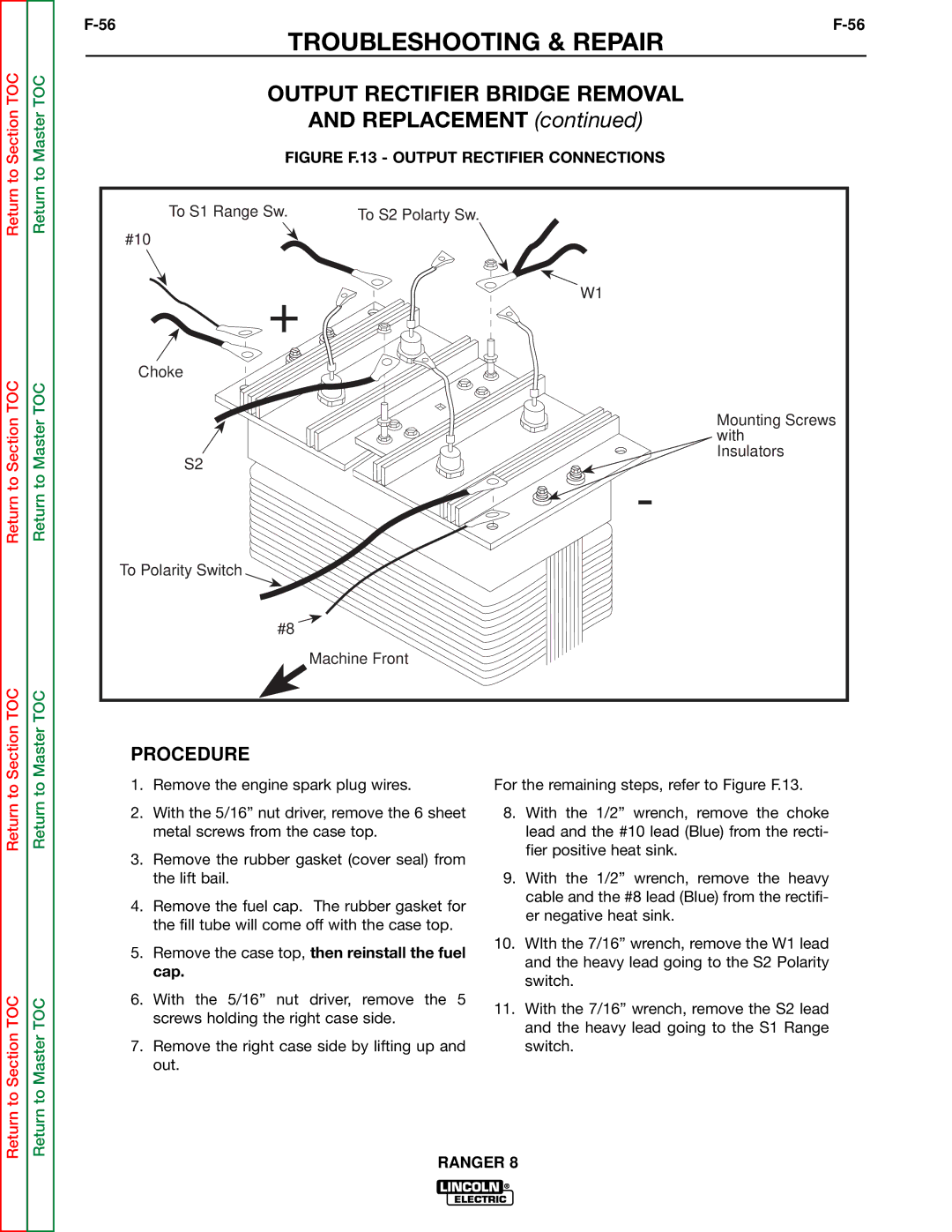
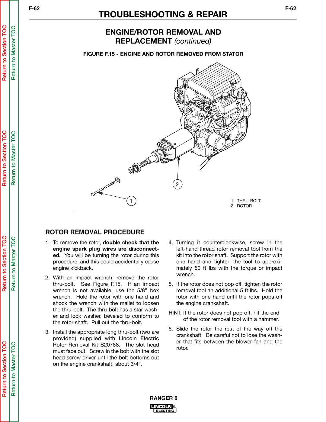
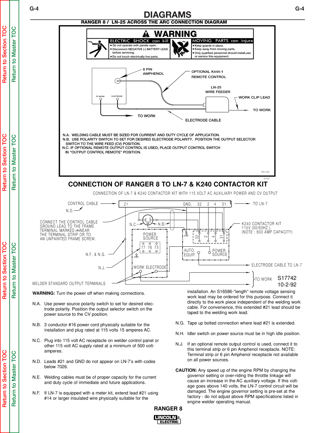
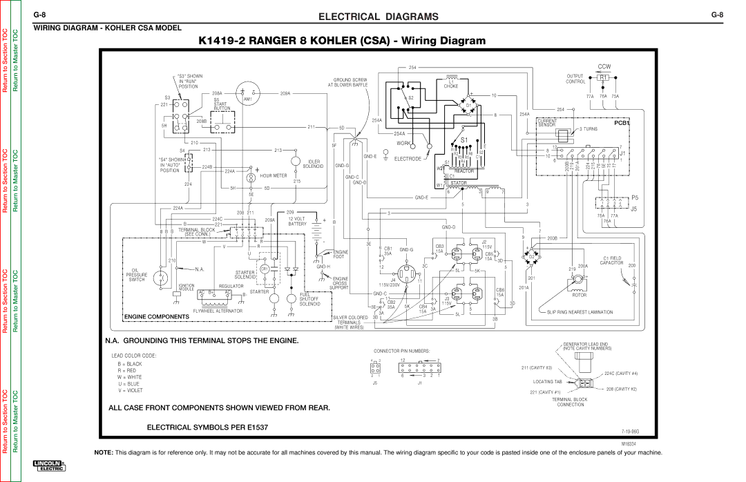
WIRING DIAGRAM - HONDA CSA MODEL |
|
|
|
|
|
|
|
|
|
|
|
|
|
|
|
|
|
|
|
|
|
|
|
|
|
|
|
|
|
|
| ||
|
|
|
|
|
|
|
|
|
|
|
| ||||||||||||||||||||||
|
|
|
|
|
|
|
|
|
|
|
|
|
| 254 |
|
|
|
|
|
|
|
|
|
|
|
|
| CCW |
|
| |||
|
| "S3" SHOWN |
|
|
|
|
|
|
| GROUND SCREW |
|
|
|
|
|
|
|
|
|
|
|
|
| OUTPUT |
| R1 |
|
|
| ||||
|
| IN "RUN" |
|
|
|
|
|
|
|
|
|
|
|
|
| L1 |
|
|
|
|
|
| CONTROL |
|
|
|
|
| |||||
|
|
|
|
|
|
|
| AT BLOWER BAFFLE |
|
|
|
|
|
|
|
|
|
|
|
|
|
|
|
|
| ||||||||
|
| POSITION |
| + | - |
|
|
|
|
|
|
|
|
| CHOKE |
|
|
|
|
|
|
|
|
|
|
|
|
|
|
| |||
|
|
|
|
|
|
|
|
|
|
|
|
|
|
|
|
|
|
|
|
|
|
|
|
|
|
|
|
| |||||
|
| S3 |
| 208A | 209A |
|
|
|
|
| S2 |
|
|
|
| + |
| 10 |
|
|
|
|
| 77A | 76A | 75A |
|
| |||||
|
|
| S5 | AM1 |
|
|
|
|
|
|
|
|
|
|
|
|
|
|
|
|
|
|
|
| |||||||||
|
|
|
|
|
|
|
|
|
|
|
|
|
|
|
|
|
|
|
|
|
|
|
|
|
|
|
|
| |||||
|
|
|
|
|
|
|
|
|
|
|
|
|
|
|
|
|
|
|
|
|
|
|
|
|
|
|
|
|
|
| |||
|
| 221 |
| START |
|
|
|
|
|
|
|
|
|
|
|
|
|
| D1 |
|
|
|
|
|
|
|
|
|
|
|
|
|
|
|
|
|
| BUTTON |
|
|
|
|
|
|
|
|
|
|
|
|
|
|
|
|
|
|
| 254 |
|
|
|
|
|
|
|
| |
|
|
|
|
| 208C |
|
|
|
|
|
|
|
|
|
|
|
| - |
|
| 8 | 254A |
|
|
|
|
|
|
|
|
| ||
|
|
| 208B |
|
|
|
|
|
| 254A |
|
|
|
|
|
|
|
|
| CURRENT |
|
|
|
|
|
|
|
| |||||
|
|
|
|
|
|
|
|
|
|
|
|
|
|
|
|
|
|
|
|
|
|
|
|
| PCB1 | ||||||||
|
| 5H |
|
|
|
|
|
|
| 211 | 5D |
|
|
|
|
|
|
|
|
|
|
|
| SENSOR |
| 3 TURNS |
|
|
|
| |||
|
|
|
|
|
|
|
|
|
|
|
|
|
|
|
|
|
|
|
|
|
|
|
|
|
|
|
|
| |||||
|
|
|
|
|
|
|
|
|
|
|
|
| 254A |
|
|
|
|
|
|
|
|
|
|
|
|
|
|
|
| ||||
|
|
|
|
|
| CB7 |
|
|
|
|
|
|
|
|
|
| S1 |
|
|
|
|
|
|
|
|
|
|
|
|
|
| ||
|
|
| 210 |
|
| 25A |
|
|
|
| 5F |
|
| WORK |
|
|
|
|
|
|
|
|
|
|
|
|
|
|
|
|
|
| |
|
|
|
|
|
|
|
|
|
|
|
|
|
|
|
|
|
| E |
|
|
| 12 |
|
|
|
|
|
| 7 |
| |||
|
| S4 |
| 213 |
|
| 213 |
|
|
|
|
|
|
|
|
| R1 |
|
|
|
| 8 |
|
|
|
|
|
|
| ||||
|
|
|
|
|
|
|
|
|
|
|
|
|
|
|
|
|
|
|
|
|
|
|
|
|
|
| |||||||
|
|
|
|
|
|
|
|
|
|
|
|
|
|
|
|
| R2 | R6 | S2 |
|
| 10 |
|
|
|
|
|
|
| J1 |
| ||
|
| "S4" SHOWN |
|
|
|
|
|
|
|
|
| ELECTRODE |
|
| R3 R5 | C1 |
|
|
| 6 |
|
|
|
|
|
| 1 |
| |||||
|
|
|
|
|
|
|
|
| IDLER |
|
|
|
| S1 | R4 |
|
|
|
|
| 201A |
|
|
|
|
| |||||||
|
| IN "AUTO" | 224B |
|
|
|
|
|
|
|
|
|
| W2 |
|
|
|
|
| 200B 219 | 224 215 | 76 5E 75 77 |
|
| |||||||||
|
|
| + |
|
| SOLENOID |
|
|
|
|
|
|
|
|
|
|
|
|
|
| |||||||||||||
|
| POSITION |
| 224A |
|
|
|
|
|
|
|
|
|
|
| REACTOR |
|
|
|
|
|
|
|
|
|
|
|
|
| ||||
|
|
|
|
|
| HOUR METER |
|
|
|
|
|
|
|
| C1 |
|
|
|
|
|
|
|
|
|
|
|
|
|
|
| |||
|
| 224 |
|
|
|
| 215 |
|
|
|
|
|
| W1 | STATOR |
|
|
|
|
|
|
|
|
|
|
|
|
|
| ||||
|
|
|
|
|
|
|
|
|
|
|
|
|
|
|
|
|
|
|
|
|
|
|
|
|
|
|
| ||||||
|
|
| 5H | 5D |
|
|
|
|
|
|
|
|
|
|
|
|
|
|
|
|
|
|
|
|
|
|
|
|
|
| |||
|
|
|
|
|
|
|
|
|
|
|
|
|
|
|
| 6 |
| 3 | 9 | 7 |
|
|
|
|
|
|
|
|
|
|
| ||
|
|
|
|
|
| 5E |
|
|
|
|
|
|
|
|
|
|
|
|
|
|
|
|
|
|
|
|
|
|
| ||||
|
|
|
|
|
|
|
|
|
|
|
|
|
|
|
|
|
|
|
|
|
|
|
|
|
|
|
|
|
|
| P5 | ||
|
|
|
|
|
|
|
|
|
|
|
|
|
|
|
|
|
|
|
|
|
|
|
|
|
|
|
|
|
|
|
| ||
|
|
|
|
|
|
|
|
|
| 12 VOLT |
|
|
|
|
|
|
|
| 5 |
|
|
|
| 3 |
|
|
|
| 1 | 2 | 3 | 4 |
|
|
| 224A |
|
|
|
|
|
|
|
|
|
|
|
|
|
|
|
|
|
|
|
|
|
|
|
|
|
|
| J5 | |||
|
|
|
|
|
|
|
|
|
|
|
|
|
|
|
|
|
|
|
|
|
|
|
|
|
|
|
|
|
|
| |||
|
|
|
| 208 | 211 |
|
|
| BATTERY |
| 3 |
|
|
|
|
|
|
|
|
|
|
|
|
|
|
|
|
|
|
| |||
211B |
|
|
|
|
|
|
|
|
|
|
|
|
|
|
|
|
|
|
|
|
|
|
|
|
| 75A | 77A |
|
| ||||
|
|
| 224C |
|
|
| 209A | + |
|
|
|
|
|
|
|
|
|
|
|
|
|
|
|
|
|
|
|
| |||||
|
|
|
|
|
|
|
|
|
|
|
|
|
|
|
|
|
|
|
|
|
|
|
|
|
| 76A |
|
| |||||
D9 |
|
|
| 221 |
|
|
|
| 209 |
|
|
|
|
|
|
|
|
|
|
|
|
|
|
|
|
|
|
|
|
| |||
4 AMP |
|
|
|
|
|
|
|
|
|
|
|
|
|
|
|
|
|
|
| 7 |
|
|
|
|
|
|
|
|
| ||||
|
| SEE DETAIL | 1 2 | 3 4 |
|
|
|
|
|
|
|
|
|
|
|
|
|
|
|
|
|
|
|
|
|
|
|
|
|
| |||
IN LINE |
|
|
| 211B |
|
|
|
|
|
|
|
|
|
|
|
|
|
|
|
|
|
|
|
|
|
|
|
| |||||
| 210 |
|
|
|
|
|
|
|
|
|
|
|
|
|
|
| 9 | 200B |
|
|
|
|
|
|
|
| |||||||
DIODE |
| NO |
|
|
|
|
|
| - |
|
|
|
|
|
|
|
|
|
| J2 |
|
|
|
|
|
|
|
|
| ||||
225A | 224E | CONNECTION |
|
| 211A | 211C |
|
| 3E |
|
|
|
|
| CB3 |
|
|
|
|
|
|
|
|
|
|
|
|
|
|
| |||
|
|
|
|
| 6 CB1 |
|
|
|
|
| 115V |
|
| + |
|
|
|
|
|
|
|
|
| ||||||||||
|
|
| 208D | 221A | 224D STARTER |
|
|
|
|
|
|
|
|
|
|
|
|
|
|
|
|
|
|
|
| ||||||||
|
|
|
|
|
|
| ENGINE |
| 35A |
|
| 15A |
|
|
| CB5 |
|
|
|
|
|
|
|
|
|
|
| ||||||
|
| 210A |
|
|
| SOLENOID |
|
|
| FOOT |
|
|
|
|
|
|
|
|
| D2 |
|
|
|
| C1 FIELD |
| |||||||
OIL |
|
|
|
|
|
|
|
|
|
|
|
|
|
|
|
| 15A | 3D |
|
|
|
|
|
| |||||||||
|
|
|
|
|
|
|
|
|
|
|
|
|
|
|
|
|
|
|
|
|
|
|
|
|
|
| |||||||
|
|
| N.A. | B/R |
|
| CR1 |
|
|
|
|
|
|
|
|
|
|
|
|
|
| - |
|
|
|
| CAPACITOR | 200 | |||||
PRESSURE |
|
|
|
|
|
|
| 12 |
|
| 3C |
|
|
|
|
|
|
| 5 |
|
| 200A | |||||||||||
|
|
| B/Y |
|
|
|
|
|
|
|
|
|
|
|
| 219 |
|
|
|
| |||||||||||||
|
|
|
|
|
|
|
|
|
|
|
| 5L |
|
|
|
|
|
|
|
| |||||||||||||
SWITCH |
|
|
| IGNITION |
|
|
|
| ENGINE |
|
|
|
|
|
|
| 5K |
|
|
|
|
|
|
|
|
|
|
| |||||
|
|
| FUEL |
|
|
|
|
|
|
|
|
|
|
|
|
|
|
|
|
|
|
|
|
|
|
|
| ||||||
|
|
| W/U | MODULE |
|
|
|
| CROSS |
|
|
|
|
|
|
|
|
|
|
|
| 201 |
|
|
| + |
|
|
|
|
| ||
|
|
|
|
| SHUTOFF |
|
|
| SUPPORT |
| J4 |
| 11 |
|
|
|
|
|
|
|
|
|
|
|
|
|
|
|
|
| |||
|
|
|
|
|
|
|
|
|
|
|
|
|
|
|
|
|
|
|
|
|
|
|
|
|
|
|
|
| |||||
|
| GY |
| W |
| SOLENOID | 5P | 212 |
|
| 115V/230V |
|
|
|
|
|
|
|
| 201A |
|
|
|
|
|
|
|
|
| ||||
|
|
|
|
|
|
|
|
|
|
|
|
|
|
|
|
|
|
| CB6 |
|
|
|
|
|
|
|
|
| |||||
|
| GY |
|
|
|
|
|
|
|
|
|
|
|
|
|
|
|
|
|
|
|
|
|
|
|
|
|
|
| ||||
|
|
|
|
|
|
|
|
|
|
|
|
|
|
|
|
|
| 15A |
|
| ROTOR |
|
|
|
|
| |||||||
|
|
|
|
|
|
|
|
|
|
|
|
|
|
| J3 |
|
|
|
|
|
|
|
|
|
| ||||||||
|
|
|
|
|
|
|
|
|
|
|
|
| 11 |
|
|
|
|
|
|
|
|
|
|
|
|
|
|
|
|
|
|
| |
20 AMP |
|
|
|
|
|
|
|
|
|
|
|
| CB2 | 5K | CB4 |
| 115V |
|
|
|
| 3D |
|
|
|
|
|
|
|
|
|
| |
CHARGE COIL |
| 1 2 3 4 5 6 |
|
| STARTER |
|
| 3E |
| 35A | 3A |
|
| 5 |
|
|
|
|
|
|
|
|
|
|
|
|
|
| |||||
|
|
|
|
| 3A |
|
|
|
|
|
|
| SLIP RING NEAREST LAMINATION |
|
| ||||||||||||||||||
|
|
|
|
|
|
|
|
|
|
| SILVER COLORED 3B |
|
| 15A |
|
| 5L |
|
|
|
|
|
|
| |||||||||
|
|
|
|
|
|
|
|
|
|
|
|
|
|
|
|
|
|
|
|
|
|
|
|
|
|
|
|
|
|
|
| ||
|
| RECTIFIER/REGULATOR |
|
|
|
|
|
|
|
|
|
|
|
|
|
|
|
| 3B |
|
|
|
|
|
|
|
|
|
|
| |||
|
|
|
|
|
|
|
| TERMINALS |
|
|
|
|
|
|
|
|
|
|
|
|
|
|
|
|
|
|
|
|
| ||||
|
|
| MODULE |
|
|
|
|
|
|
|
|
|
|
|
|
|
|
|
|
|
|
|
|
|
|
|
|
|
|
|
| ||
|
|
|
|
| B |
|
|
| (WHITE WIRES) |
|
|
|
|
|
|
|
|
|
|
|
|
|
|
|
|
|
|
|
|
|
| ||
HONDA ENGINE COMPONENTS |
|
|
|
|
|
|
|
|
|
|
|
|
|
|
|
|
|
|
|
|
|
|
|
|
|
|
|
| |||||
|
|
|
|
|
|
|
|
|
|
|
|
|
|
|
|
|
|
|
|
|
|
|
|
| GENERATOR LEAD END |
|
|
| |||||
|
|
|
|
|
|
|
|
|
|
| CONNECTOR PIN NUMBERS: |
|
|
|
|
|
|
|
| (NOTE CAVITY NUMBERS) |
|
| |||||||||||
N.A. GROUNDING THIS TERMINAL STOPS THE ENGINE. |
|
|
|
|
|
|
|
|
|
|
|
|
|
|
|
|
|
| |||||||||||||||
| 4 | 3 |
| 12 |
|
| 7 |
|
|
|
|
|
|
|
|
|
|
|
|
|
|
|
| ||||||||||
|
|
|
|
|
|
|
|
|
|
|
|
|
|
|
|
|
|
|
|
|
|
|
|
|
|
|
|
|
| ||||
LEAD COLOR CODE: |
|
|
|
|
|
|
|
|
|
|
|
|
|
|
|
|
|
|
|
|
| 211 (CAVITY #3) |
|
|
|
|
|
|
|
| |||
|
|
|
|
|
|
|
|
| 2 | 1 |
| 6 | 3 | 2 | 1 |
|
|
|
|
|
|
|
|
|
|
|
| 224C (CAVITY #4) | |||||
|
|
|
|
|
|
|
|
|
|
|
|
|
|
|
|
|
|
|
|
|
|
|
| ||||||||||
B = BLACK OR GRAY |
|
|
|
|
|
|
|
|
|
|
|
|
|
|
|
|
|
|
|
|
|
|
|
|
| ||||||||
|
|
|
|
|
|
|
| J5 |
|
|
| J1 |
|
|
|
|
|
|
|
| LOCATING TAB |
|
|
|
|
|
|
|
| ||||
R = RED OR PINK |
|
|
|
|
|
|
|
|
|
|
|
|
|
|
|
|
|
|
|
|
|
|
|
|
|
|
|
| |||||
|
|
|
|
|
|
|
|
|
|
|
|
|
|
|
|
|
|
|
|
|
|
|
|
|
|
|
|
|
| ||||
|
|
|
|
|
|
|
|
|
|
|
|
|
|
|
|
|
|
|
|
|
|
|
|
|
|
|
| 208 (CAVITY #2) | |||||
W = WHITE |
|
|
|
|
|
|
|
|
|
|
|
|
|
|
|
|
|
|
|
|
|
|
| 221 (CAVITY #1) |
|
|
|
| |||||
|
|
|
|
|
|
|
|
|
|
|
|
|
|
|
|
|
|
|
|
|
|
|
|
|
|
|
|
|
|
| |||
U = BLUE |
|
|
|
|
|
|
|
|
|
|
|
|
|
|
|
|
|
|
|
|
|
|
|
| TERMINAL BLOCK |
|
|
|
|
| |||
GY = GRAY |
|
|
|
|
|
|
|
|
|
|
|
|
|
|
|
|
|
|
|
|
|
|
|
| CONNECTION |
|
|
|
|
|
| ||
|
|
|
|
|
|
|
|
|
|
|
|
|
|
|
|
|
|
|
|
|
|
|
|
|
|
|
|
|
|
|
|
| |
ALL CASE FRONT COMPONENTS SHOWN VIEWED FROM REAR. |
|
|
|
|
|
|
|
|
|
|
|
|
|
|
|
|
|
|
|
|
|
| |||||||||||
| ELECTRICAL SYMBOLS PER E1537 |
|
|
|
|
|
|
|
|
|
|
|
|
|
|
|
|
|
|
|
|
|
|
|
|
|
| A | |||||
M19988
NOTE: This diagram is for reference only. It may not be accurate for all machines covered by this manual. The wiring diagram specific to your code is pasted inside one of the enclosure panels of your machine.