


Return to Section TOC
Return to Section TOC
Return to Master TOC
Return to Master TOC
TROUBLESHOOTING & REPAIR
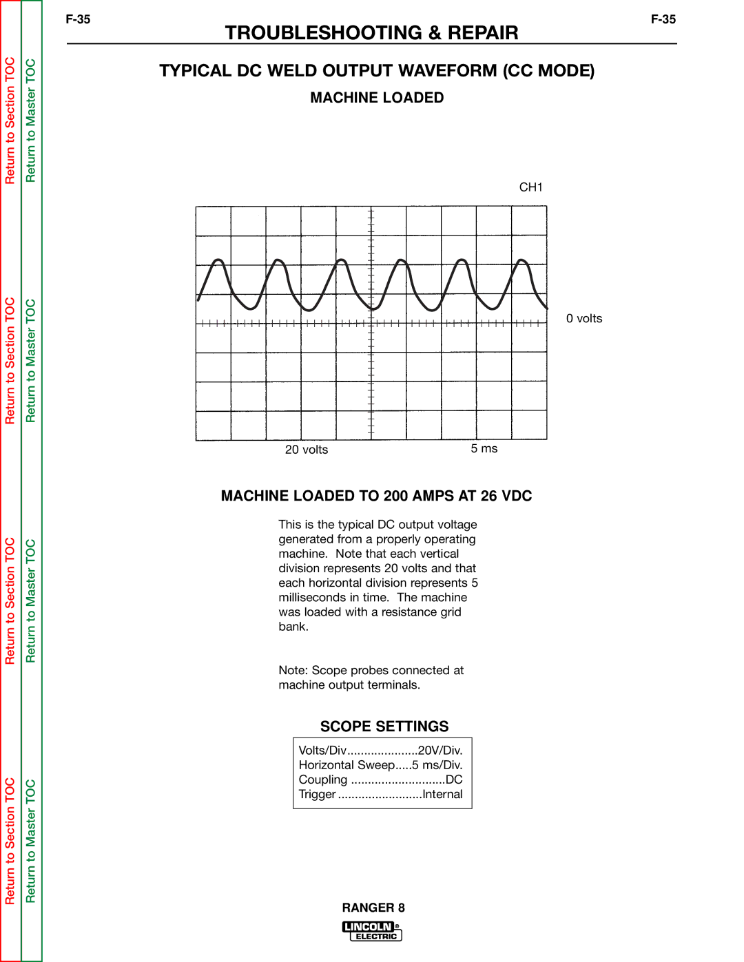
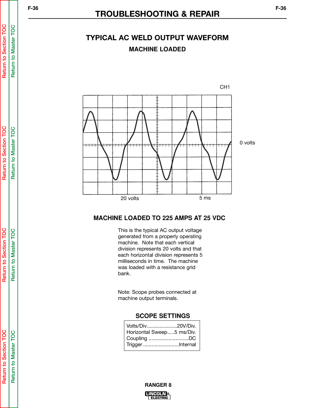
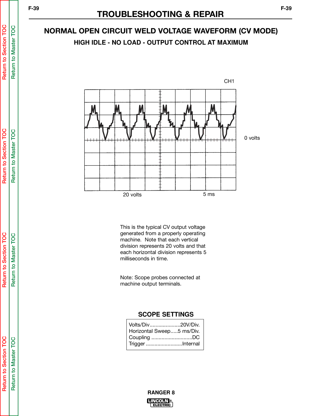
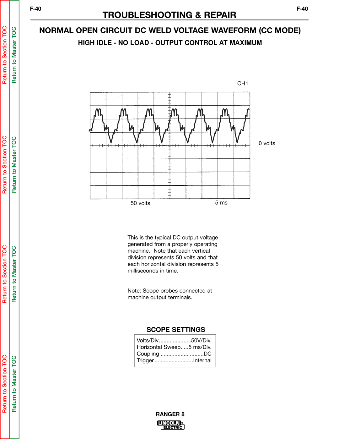
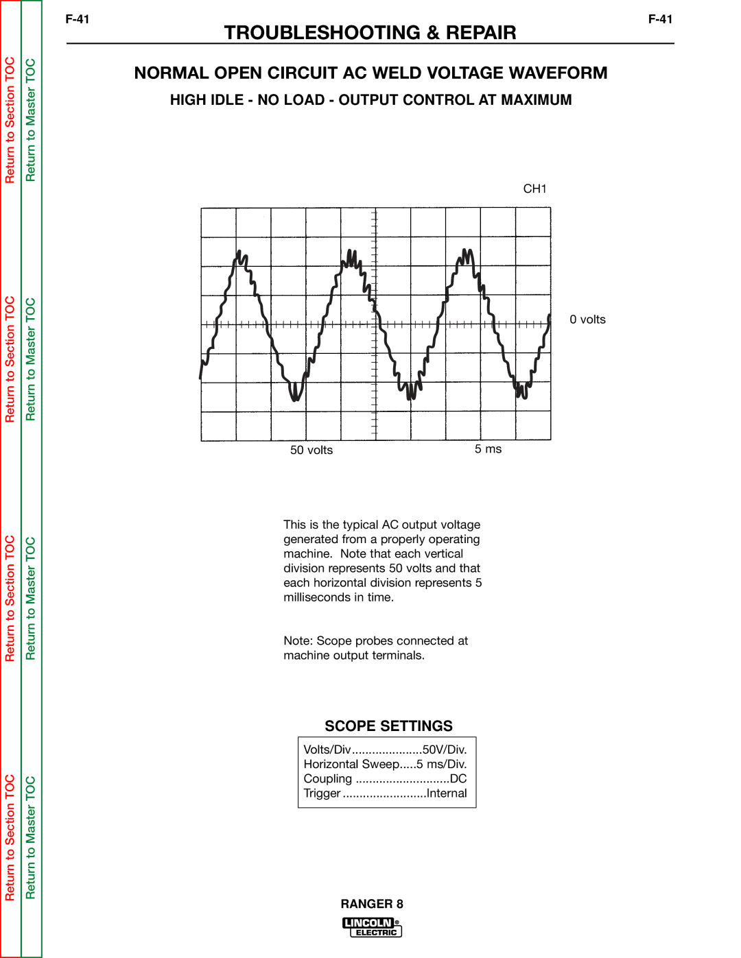
OUTPUT RECTIFIER BRIDGE TEST (continued)
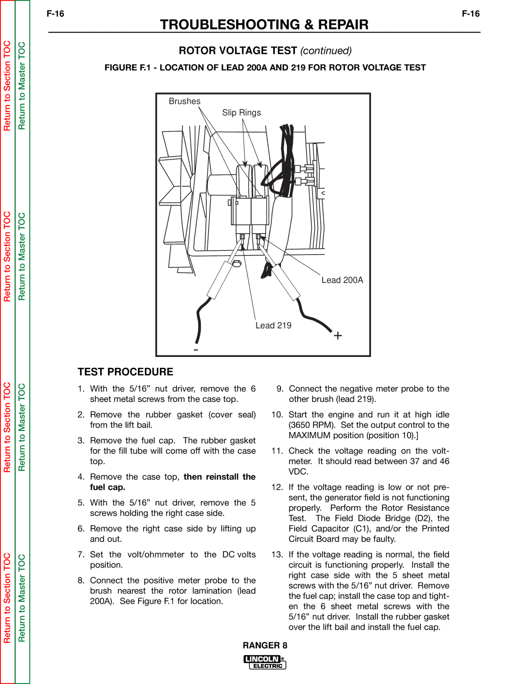
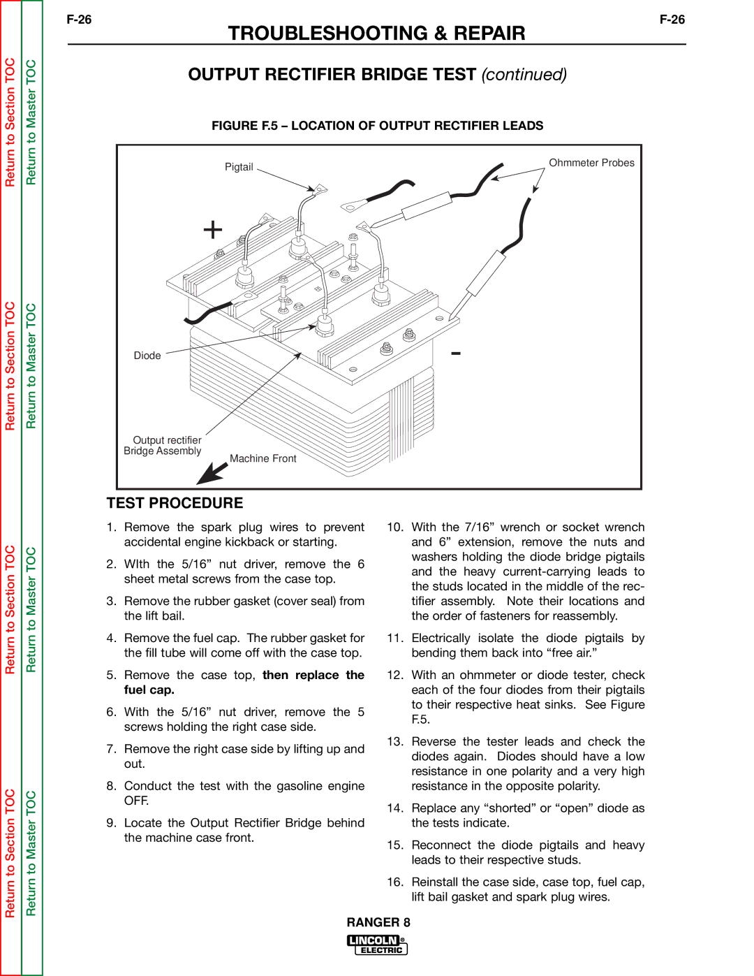
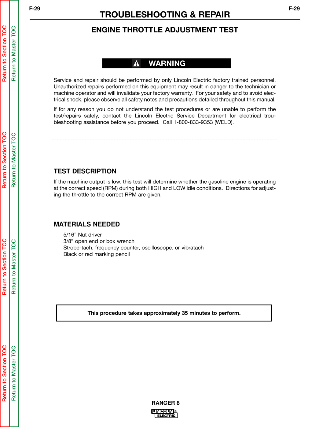
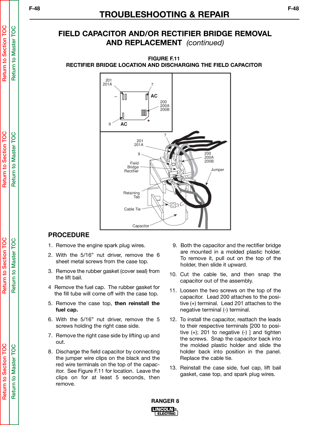
FIGURE F.5 – LOCATION OF OUTPUT RECTIFIER LEADS
Pigtail | Ohmmeter Probes |
|
+ |
Diode | - |
|
Output rectifier
Bridge Assembly
Machine Front
Return to Section TOC
Return to Section TOC
Return to Master TOC
Return to Master TOC
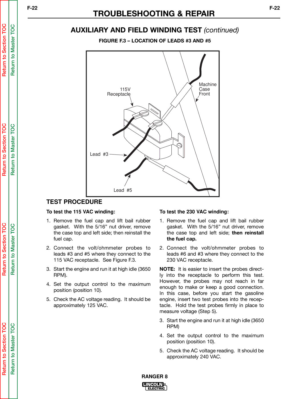
TEST PROCEDURE
1.Remove the spark plug wires to prevent accidental engine kickback or starting.
2.WIth the 5/16” nut driver, remove the 6 sheet metal screws from the case top.
3.Remove the rubber gasket (cover seal) from the lift bail.
4.Remove the fuel cap. The rubber gasket for the fill tube will come off with the case top.
5.Remove the case top, then replace the fuel cap.
6.With the 5/16” nut driver, remove the 5 screws holding the right case side.
7.Remove the right case side by lifting up and out.
8.Conduct the test with the gasoline engine OFF.
9.Locate the Output Rectifier Bridge behind the machine case front.
10.With the 7/16” wrench or socket wrench and 6” extension, remove the nuts and washers holding the diode bridge pigtails and the heavy
11.Electrically isolate the diode pigtails by bending them back into “free air.”
12.With an ohmmeter or diode tester, check each of the four diodes from their pigtails to their respective heat sinks. See Figure F.5.
13.Reverse the tester leads and check the diodes again. Diodes should have a low resistance in one polarity and a very high resistance in the opposite polarity.
14.Replace any “shorted” or “open” diode as the tests indicate.
15.Reconnect the diode pigtails and heavy leads to their respective studs.
16.Reinstall the case side, case top, fuel cap, lift bail gasket and spark plug wires.