


INSTALLATION
Return to Section TOC
Return to Section TOC
Return to Section TOC
Return to Master TOC
Return to Master TOC
Return to Master TOC
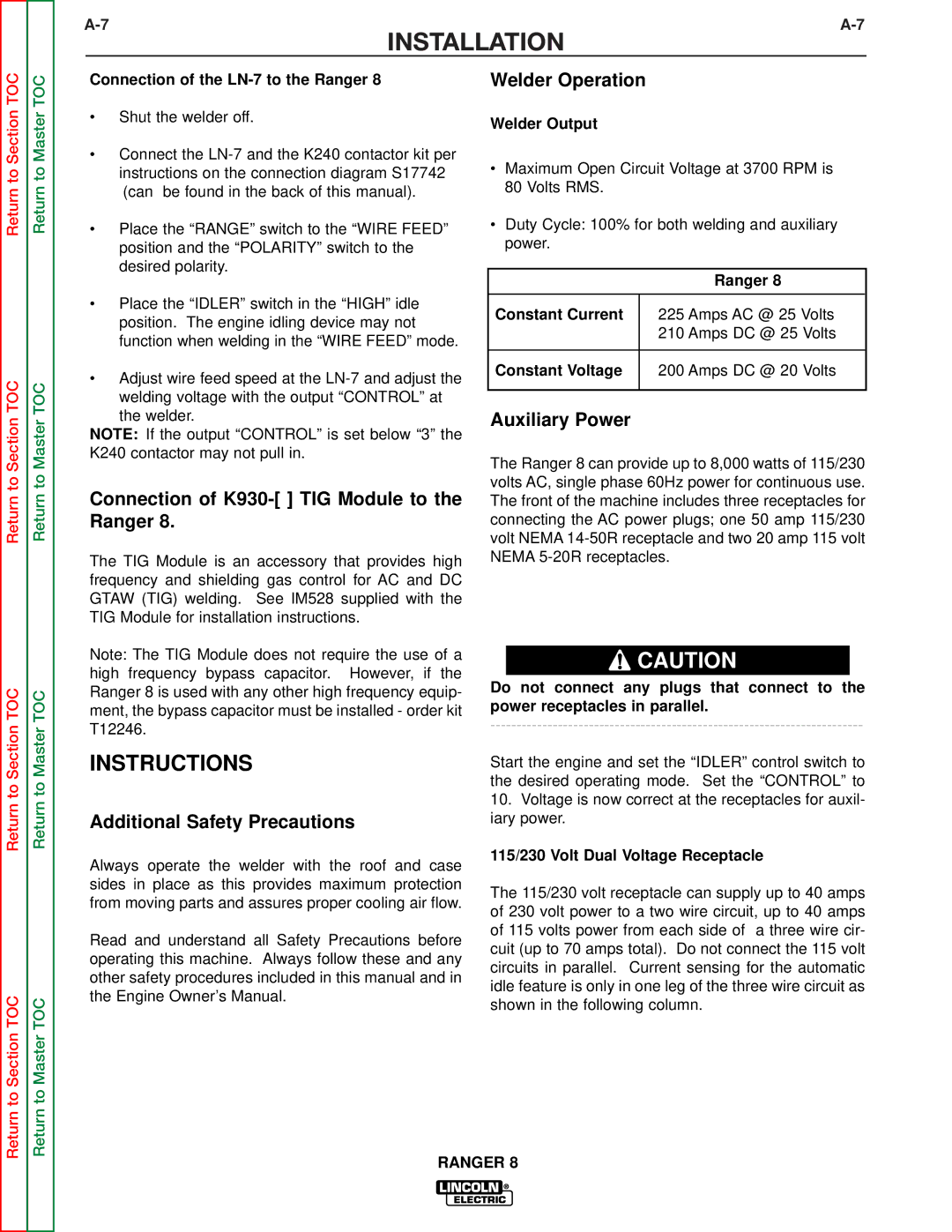
Auxiliary Power While Welding
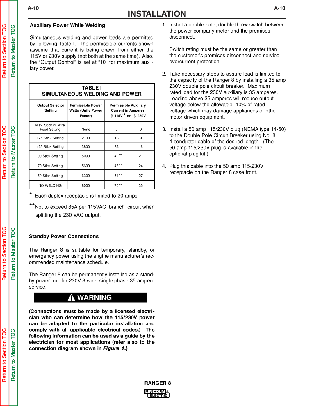
Simultaneous welding and power loads are permitted by following Table I. The permissible currents shown assume that current is being drawn from either the 115V or 230V supply (not both at the same time). Also, the “Output Control” is set at “10” for maximum auxil- iary power.
TABLE I
SIMULTANEOUS WELDING AND POWER
Output Selector | Permissible Power | Permissible Auxiliary |
| ||
Setting | Watts (Unity Power | Current in Amperes | |||
| Factor) | @ 115V | |||
|
|
|
|
|
|
Max. Stick or Wire |
|
|
|
|
|
Feed Setting | None | 0 | 0 |
|
|
|
|
|
|
|
|
175 Stick Setting | 2100 | 18 | 9 |
|
|
|
|
|
|
|
|
125 Stick Setting | 3800 | 32 | 16 |
|
|
|
|
|
|
|
|
90 Stick Setting | 5000 | 42** | 21 |
|
|
|
|
|
|
|
|
70 Stick Setting | 5600 | 48** | 24 |
|
|
|
|
|
|
|
|
50 Stick Setting | 6300 | 54** | 27 |
|
|
|
|
|
|
|
|
NO WELDING | 8000 | 70** | 35 |
|
|
|
|
|
|
|
|
*Each duplex receptacle is limited to 20 amps.
**Not to exceed 35A per 115VAC branch circuit when
splitting the 230 VAC output.
Standby Power Connections
The Ranger 8 is suitable for temporary, standby, or emergency power using the engine manufacturer’s rec- ommended maintenance schedule.
The Ranger 8 can be permanently installed as a stand- by power unit for
![]() WARNING
WARNING
1.Install a double pole, double throw switch between the power company meter and the premises disconnect.
Switch rating must be the same or greater than the customer’s premises disconnect and service overcurrent protection.
2.Take necessary steps to assure load is limited to the capacity of the Ranger 8 by installing a 35 amp 230V double pole circuit breaker. Maximum rated load for the 230V auxiliary is 35 amperes. Loading above 35 amperes will reduce output voltage below the allowable
3.Install a 50 amp 115/230V plug (NEMA type
4 conductor cable of the desired length. (The
50 amp 115/230V plug is available in the optional plug kit.)
4.Plug this cable into the 50 amp 115/230V receptacle on the Ranger 8 case front.
Return to Section TOC
Return to Master TOC
(Connections must be made by a licensed electri- cian who can determine how the 115/230V power can be adapted to the particular installation and comply with all applicable electrical codes.) The following information can be used as a guide by the electrician for most applications (refer also to the connection diagram shown in Figure 1.)
RANGER 8