Lincoln Electric SVM107-B service manual Auxiliary and Field Winding Test, Test Description

Page 61

Return to Section TOC

Return to Section TOC

Return to Section TOC

Return to Section TOC

Return to Master TOC

Return to Master TOC

Return to Master TOC

Return to Master TOC

F-21

F-21

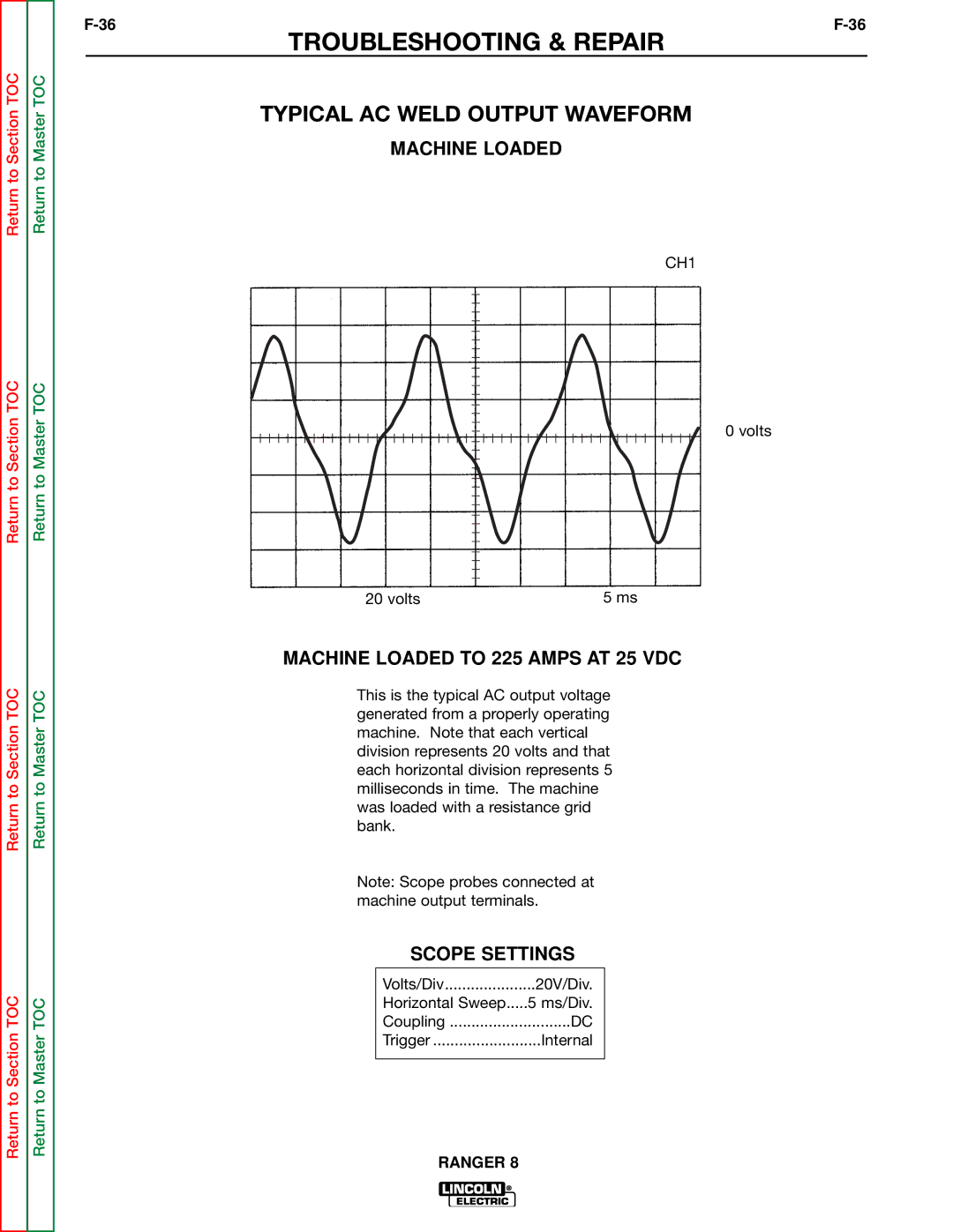
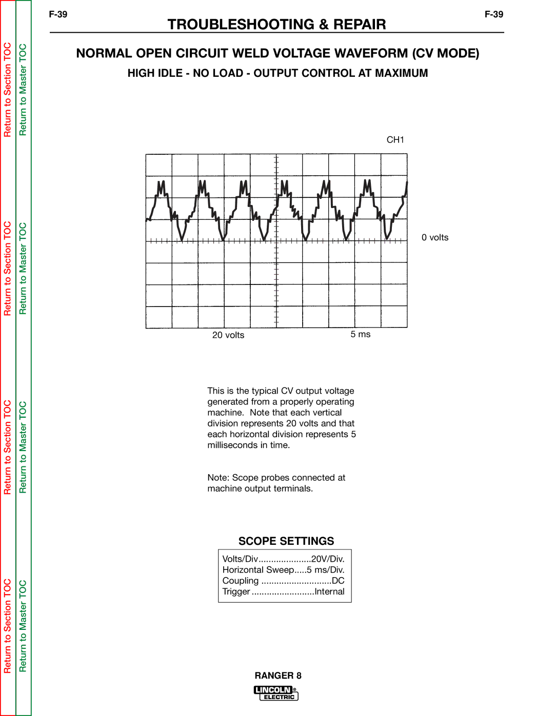
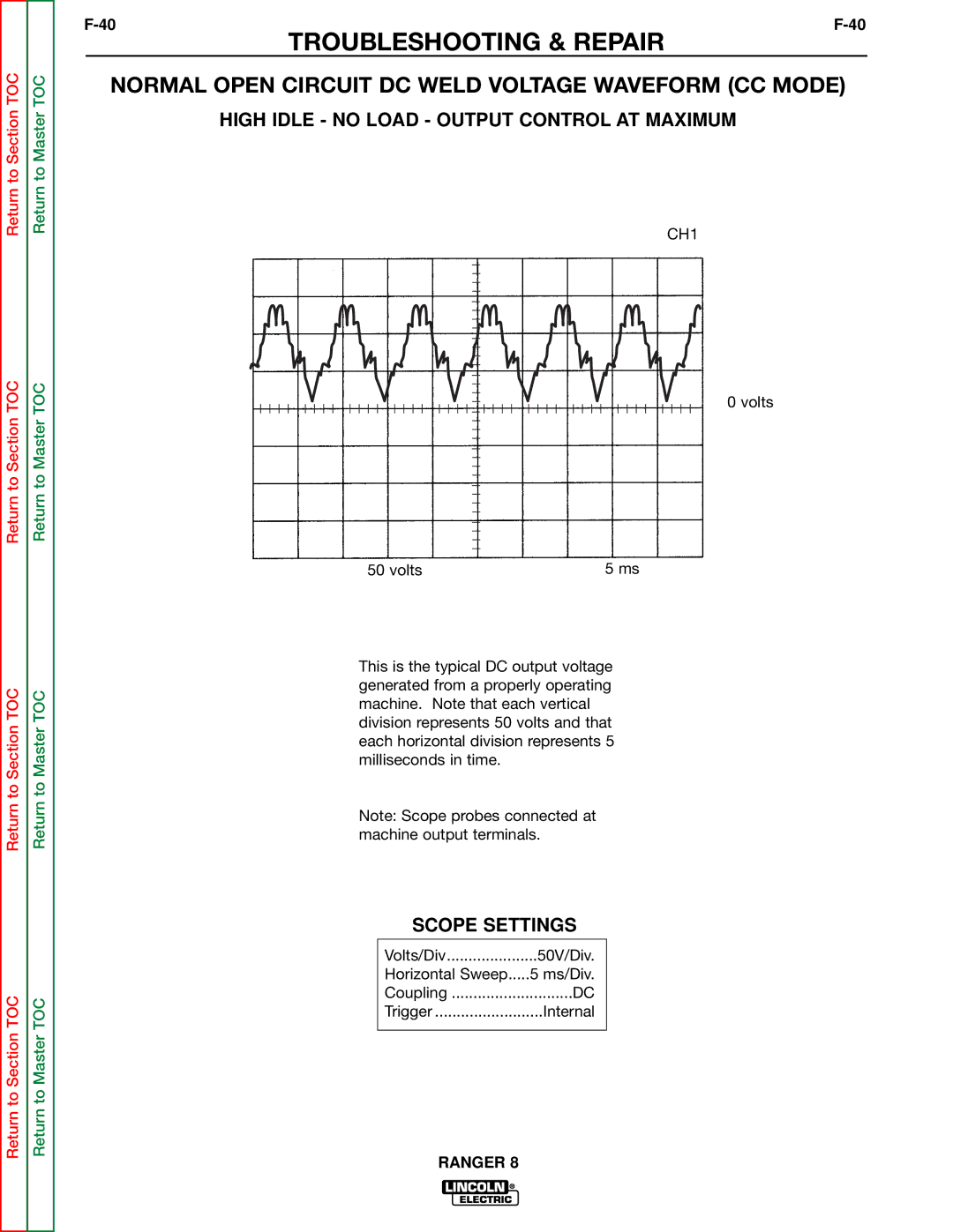
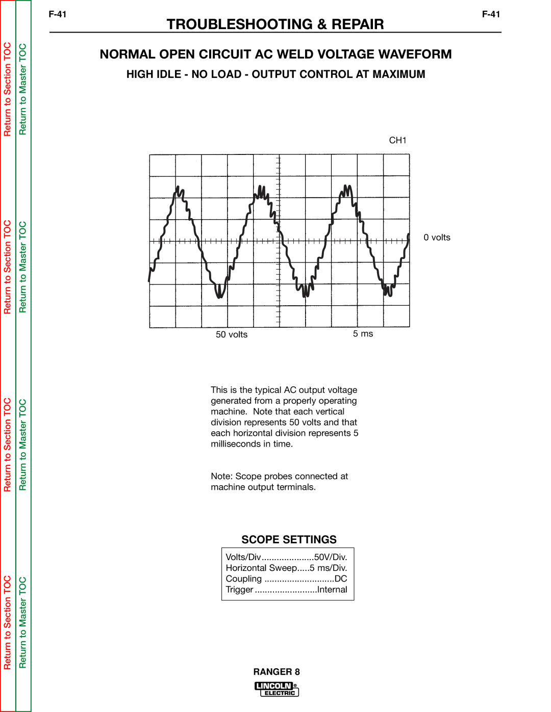
TROUBLESHOOTING & REPAIR

AUXILIARY AND FIELD WINDING TEST

WARNING

Service and repair should be performed by only Lincoln Electric factory trained personnel. Unauthorized repairs performed on this equipment may result in danger to the technician or machine operator and will invalidate your factory warranty. For your safety and to avoid elec- trical shock, please observe all safety notes and precautions detailed throughout this manual.

If for any reason you do not understand the test procedures or are unable to perform the test/repairs safely, contact the Lincoln Electric Service Department for electrical trou- bleshooting assistance before you proceed. Call 1-800-833-9353 (WELD).

TEST DESCRIPTION

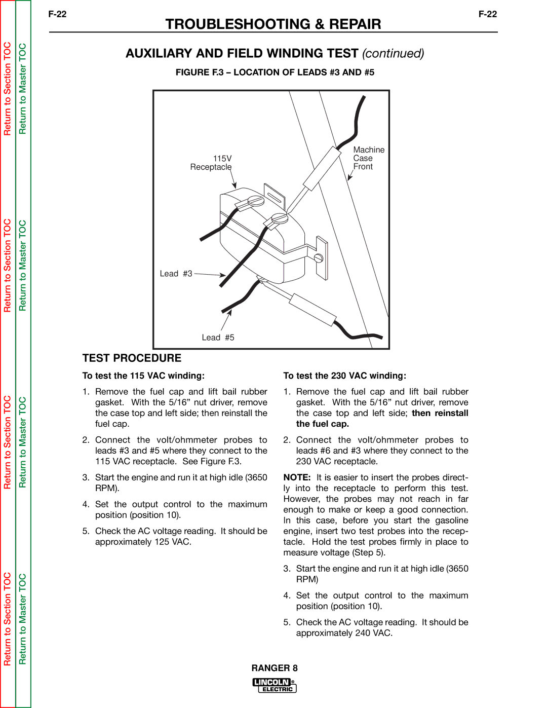
This test will determine if the correct AC voltages are being generated from the stator windings.

MATERIALS NEEDED

Volt/Ohmmeter 5/16” Nut driver Wiring Diagram

This procedure takes approximately 30 minutes to perform.

RANGER 8

Image 61
Contents Rangertm Safety Electric Shock can kill Iii Welding Sparks can cause fire or explosionPrécautions DE Sûreté Master Table of Contents for ALL Sections Table of Contents Installation Section Welding Output Auxiliary Power50 100 150 200 20 B50 100 150 200 250 300 350 Output Amps Installation Instructions Oil Battery ConnectionsAWG FuelAngle of Operation Welder Output Connection of the LN-7 to the RangerRanger Constant CurrentMotor Starting Duplex ReceptaclesType Common Electrical Devices Possible Concerns Electrical Device USE with the RangerStandby Power Connections Auxiliary Power While WeldingFigure A.1 Connection of Ranger 8 to Premises WiringRanger Table of Contents Operation Section AC/DC Stick Welding Constant Current DC Semiautomatic Wire Feed Welding Constant VoltageAC/DC TIG Welding Constant Current Provides a fine welding current adjustment within Control SwitchRange Switch settings in the STICK/TIG mode Welding voltage control with the Range switch setStopping the Engine Starting/Shutdown InstructionsStick Constant Current Welding Wire Feed Welding Processes Constant VoltageTIG Constant Current Welding Stick Auto Summary of Welding ProcessesSection C-1Section C-1 Accessories Recommended Equipment Ranger Table of Contents Maintenance Engine OIL Change Routine MaintenanceEngine OIL Refill Capacities Kohler Onan HondaOIL Filter Change Engine Maintenance Parts Engine AdjustmentsPre-Cleaner Slip RingsFigure D.1 Major Component Locations Ranger Table of Contents Theory of Operation Section Theory of Operation Rotor Field Feedback and Auxiliary Power Weld WINDING, REACTOR, Range Switch Output BRIDGE, Choke Polarity SWITCH, and Output Terminals Ranger Table of Contents Trouble Shooting & Repair Section HOW to USE Troubleshooting Guide Troubleshooting & RepairStatic-Sensitive PC board can be damaged by static electricityDevices Handle only atOutput Problems Troubleshooting GuideDetailed in the beginning of this manual Observe Safety GuidelinesTroubleshooting & Repair Troubleshooting & Repair Troubleshooting Guide Troubleshooting & Repair Engine Problems Troubleshooting & Repair Troubleshooting & Repair Welding Problems Ranger Test Description Rotor Voltage TestMaterials Needed Test Procedure Rotor Resistance Test Rotor Resistance Test Troubleshooting & Repair Ranger Auxiliary and Field Winding Test To test the 230 VAC winding To test the 115 VAC windingTo test the field winding Ranger Output Rectifier Bridge Test Output Rectifier Bridge Test Charging Circuit Test Charging Circuit Test Engine Throttle Adjustment Test Engine Throttle Adjustment Test Engine Throttle Adjustment Test Oscilloscope Method Normal Open Circuit Voltage Waveform 115 VAC Supply Scope SettingsHigh Idle no Load Output Control AT Maximum Machine Loaded Typical DC Weld Output Waveform CV ModeMachine Loaded to 200 Amps AT 26 VDC Typical DC Weld Output Waveform CC ModeMachine Loaded to 225 Amps AT 25 VDC Typical AC Weld Output WaveformAbnormal Open Circuit Weld Voltage Waveform CV Mode Abnormal Open Circuit DC Weld Voltage Waveform Normal Open Circuit Weld Voltage Waveform CV Mode Normal Open Circuit DC Weld Voltage Waveform CC Mode Normal Open Circuit AC Weld Voltage Waveform Ranger Description Brush Removal and ReplacementProcedure Brush Removal and ReplacementFigure F.10 Brush LEADS/BRUSHES Retained with Cable TIE Slip RingsRanger Field Capacitor AND/OR Rectifier Bridge Removal Replacement Field Capacitor AND/OR Rectifier Bridge Removal ReplacementProcedure Rectifier Bridge Removal and Replacement Ranger Printed Circuit Board Removal Replacement Procedure Printed Circuit Board Removal and ReplacementPrinted Circuit Board Removal Ranger Output Rectifier Bridge Removal Replacement Output Rectifier Bridge Removal Remove the case top, then reinstall the fuel capSection TOC Ranger Instructions ENGINE/ROTOR Removal and ReplacementFigure F.14 Component LOCATIONS, ENGINE/ROTOR Removal ENGINE/ROTOR RemovalEngine and Rotor Removal Procedure Figure F.15 Engine and Rotor Removed from Stator Rotor Removal ProcedureReassembly Procedure Replacement KIT S20788Retest After Repair Table of Contents Diagrams Section Dimension RANGER8 Dimension Print Ranger 8 Honda & KohlerConnection of Ranger 8 to LN-7 & K240 Contactor KIT DiagramsWiring Diagram Onan NON CSA Model Electrical DiagramsWiring Diagram Onan CSA Model K1418-2 Ranger 8 Onan CSA Version Wiring DiagramWiring Diagram Kohler NON CSA Model K1419-1 Ranger 8 Kohler Wiring DiagramWiring Diagram Kohler CSA Model K1419-2 Ranger 8 Kohler CSA Wiring DiagramK2160-1 Ranger 8 Honda CSA Wiring Diagram 16482 Schematic IDLER/CONTROL PC BoardPC Board Assembly IDLER/CONTROL SVM Error Reporting Form