


Return to Section TOC
Return to Section TOC
Return to Master TOC
Return to Master TOC
TROUBLESHOOTING & REPAIR
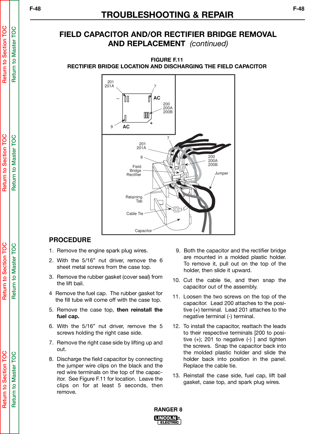
OUTPUT RECTIFIER BRIDGE REMOVAL
AND REPLACEMENT (continued)
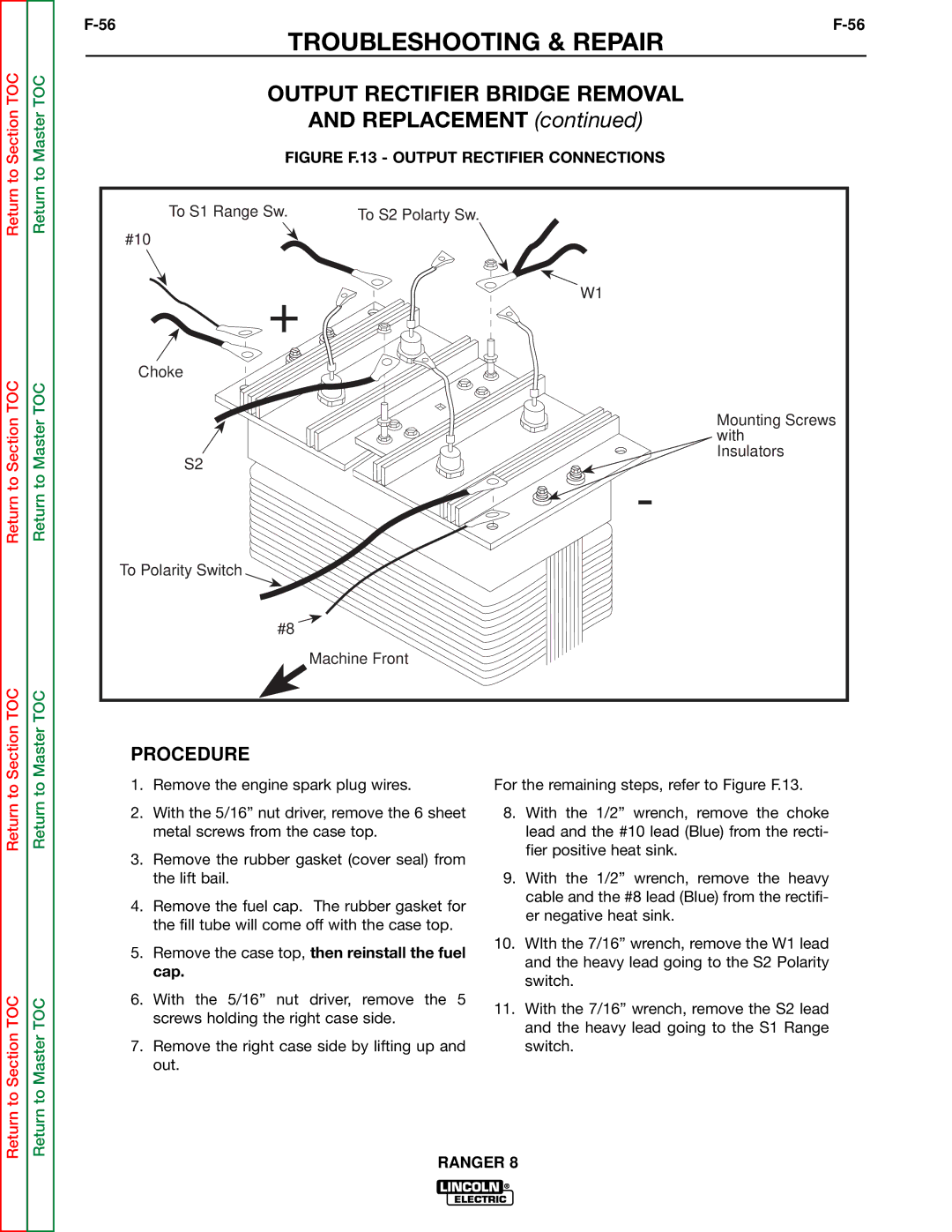
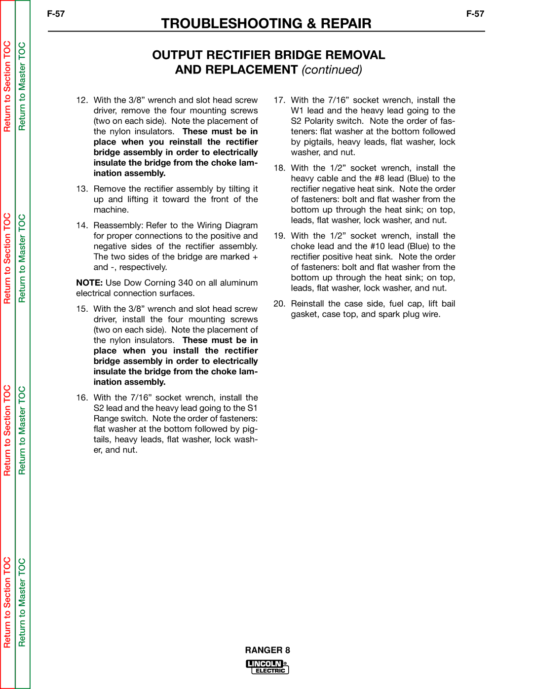
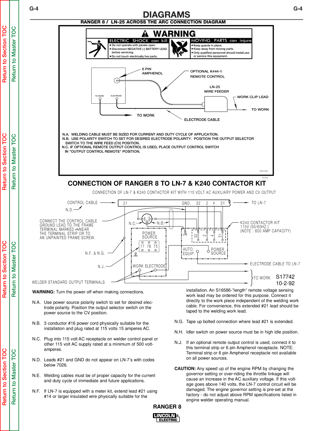
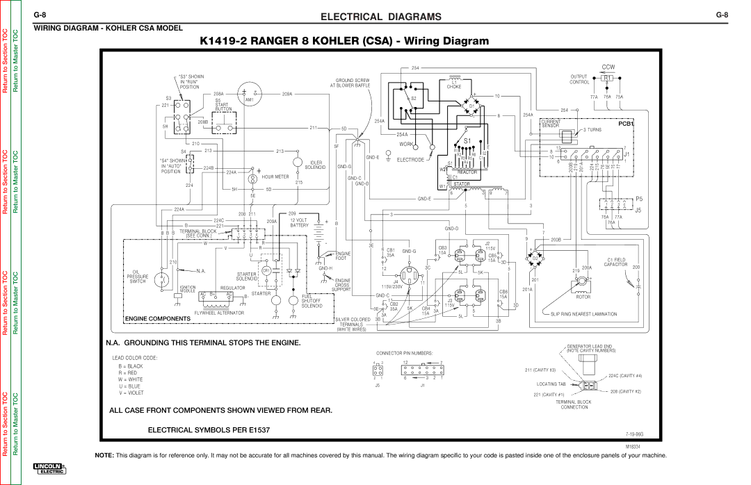
FIGURE F.13 - OUTPUT RECTIFIER CONNECTIONS
To S1 Range Sw. | To S2 Polarty Sw. |
#10 |
|
+ | W1 |
| |
Choke |
|
Mounting Screws
with
Insulators
S2
-
To Polarity Switch
#8
Machine Front
Return to Section TOC
Return to Section TOC
Return to Master TOC
Return to Master TOC
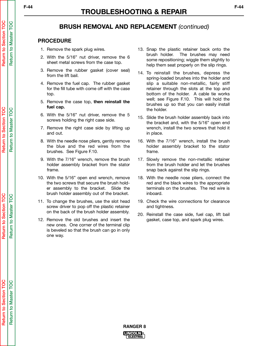
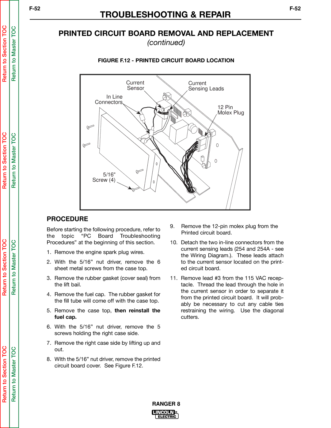
PROCEDURE
1.Remove the engine spark plug wires.
2.With the 5/16” nut driver, remove the 6 sheet metal screws from the case top.
3.Remove the rubber gasket (cover seal) from the lift bail.
4.Remove the fuel cap. The rubber gasket for the fill tube will come off with the case top.
5.Remove the case top, then reinstall the fuel cap.
6.With the 5/16” nut driver, remove the 5 screws holding the right case side.
7.Remove the right case side by lifting up and out.
For the remaining steps, refer to Figure F.13.
8.With the 1/2” wrench, remove the choke lead and the #10 lead (Blue) from the recti- fier positive heat sink.
9.With the 1/2” wrench, remove the heavy cable and the #8 lead (Blue) from the rectifi- er negative heat sink.
10.WIth the 7/16” wrench, remove the W1 lead and the heavy lead going to the S2 Polarity switch.
11.With the 7/16” wrench, remove the S2 lead and the heavy lead going to the S1 Range switch.