Emerson XDR user manual European Union Fluorinated Greenhouse Gas Requirements

Page 20

Piping

6.0PIPING

Refer to site-specific drawings for general locations of the piping connections. The drawings should specify where the piping connects to the Liebert XDR.

6.1European Union Fluorinated Greenhouse Gas Requirements

Stationary air conditioning, refrigeration, heat pump equipment and stationary fire protection sys- tems in the European Community market and operating with fluorinated greenhouse gases (f-gas), such as R407C, R-134a, R410A, must comply with the F-Gas Regulation: (EC) No. 842/2006 (F-gas). The regulation prohibits, among other actions, venting fluorinated greenhouse gases to the atmo- sphere.

The F-Gas Regulation requires operators to use all measures that are technically feasible and do not entail disproportionate cost to prevent leakage of these gases, to test for leakage regularly and to recover f-gas before disposing of equipment, as well as during service and maintenance.

Refer to the full regulation for additional details.

6.2System Connection Configuration

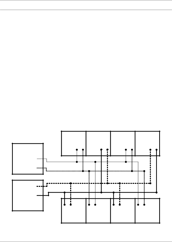
If possible, connect the Liebert XDR modules to Liebert XDPs or Liebert XDCs in an interlaced configuration (see Figure 12). In an interlaced configuration, half the cooling modules in an aisle are connected to one Liebert XDP or Liebert XDC and the other half in that aisle are connected to another Liebert XDP or Liebert XDC. Interlacing the connection piping will keep half the Liebert XDR modules operating and maintain cooling in the conditioned space should one of the Liebert XDP or Liebert XDC units fail.

However, if this is not possible, connect the Liebert XDR modules in a non-interlaced configuration (see Figure 13).

Figure 12 Typical Liebert XDR piping—interlaced connections

TOP VIEW

DRAWING IS


NOT TO SCALE

Liebert

Liebert

Liebert

Liebert


XDR A

XDR B

XDR A

XDR B

Liebert XDP/


Liebert XDC A


Supply


Return


Return


Supply


Liebert XDP/

Liebert XDC B

NOTE: Line size does NOT indicate pipe size difference .

Liebert

XDR B

Liebert

XDR A

Liebert

XDR B

Liebert

XDR A

14

Image 20
Contents Liebert XDR Important Safety Guidelines Fluorinated Greenhouse Gas Requirements-European UnionTable of Contents Installation Checklist and System Fill for Startup SpecificationsFigures Page Example XDR20B1R Component Locations and Model Number NomenclaturePre-Installation Checks Installation ConsiderationsReferences Packing ListProduct/System Description Checking and UnpackingRecyclable Packaging Module HandlingUnpacking the Module Removing packaging Removing the Liebert XDR from the Pallet Remove Liebert XDR from palletLiebert XDR Dimensions Move the Liebert XDROverall dimensions with one-shot coupling pre-charged Determining Placement in the Conditioned Space Overall dimensions with removable couplingGeneric airflow diagram AirflowInstalling the Rack-Mounting Kit onto the Rack Mounting the Liebert XDR on the Rack-Mounting KitDoor Safety Catch System Connection Configuration European Union Fluorinated Greenhouse Gas RequirementsConnection Methods and Points InsulationRecommended Piping Size Hard-Piped Connection SizesBrazing Preparations Leak-Checking and Evacuation Header System Refer to for detailsDegree Connection TOP View Tools Required Male coupling on Liebert XD cooling moduleHex body, union nut on one-shot coupling Connection Methods-Removable Couplings Removable couplings Return Main Supply Main Oil rings on header and Liebert XD Flex Pipe connectors Do not Overtighten Disconnect a Liebert XD Flex Pipe from a Liebert XD System Piping mains without Liebert XD Flex PipeDisconnecting the Liebert XD Flex Pipe from the Liebert XDR Removing the Liebert XDR from a CabinetChecklist for Proper Installation Charging with RefrigerantStarting the Liebert XD System Maintenance Fluorinated Greenhouse Gas RequirementsSpecifications Page Ne t