Delta Essential Maintenance for Your Planer: Brush Inspection and Lubrication Tips

Page 15

BRUSH INSPECTION AND

REPLACEMENT

Disconnect tool from power source

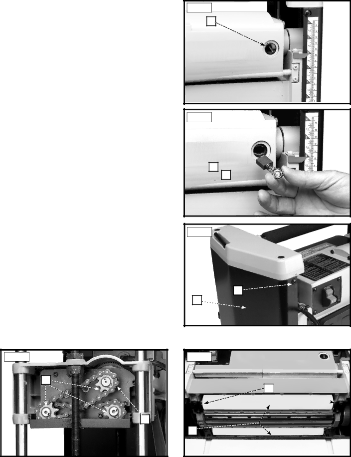
Brush life varies. It depends on the load on the motor. Check the brushes after the first 50 hours of use for a new machine or after a new set of brushes has been installed. After the first check, examine them after about 10 hours of use until such time that replacement is necessary.

The brush holders, one of which is shown at (A) Fig. 27, are located on the motor housing opposite each other. One of the brushes, removed for inspection, is illustrated in Fig. 28. When the carbon (B) on either brush is worn to 3/16" in length or if either spring (C) or shunt wire is burned or damaged in any way, replace both brushes. If the brushes are found serviceable after removing, re- install them in the same position as removed.

After brush maintenance is completed, the cutterhead guard must be re-installed before starting the planer.

LUBRICATION

The gears in the gear box and the feed roller bushings should be lubricated periodically.

Disconnect tool from power source.

1.Remove the screw (A) Fig. 29, and nut located on the other end of screw. Remove the side cover (B) from the left side of the planer.

2.Place a light coat of E.P. multi-purpose grease on the teeth of the gears (C) Fig. 30, and a light coat of spray lubricant on the chains (F). Replace the side cover.

3.Place the planer on its back and squirt oil on the feed roller bushings (D) Fig. 31 at each end of the feed rollers (E).

Fig. 30

C

F

Fig. 27

A

Fig. 28

B

C

Fig. 29

A

B

Fig. 31

D

E

15

Image 15
Contents Contractors Saw Important Safety Instructions Table of ContentsCalifornia Proposition Safety Guidelines DefinitionsStay ALERT, Watch What YOU are Doing General Safety RulesRefer to them often and use them to instruct others Additional Specific Safety RulesPower Connections Motor SpecificationsGrounding Instructions Functional Description Carton ContentsRaising and Lowering Handle AssemblyAssembly Tools Required Assembly Time EstimateStarting and Stopping Planer OperationCutterhead Guard Fastening Planer to Supporting SurfaceRaising and Lowering Head Assembly Locking Switch in the OFF PositionLeveling Extension Tables Knife Transfer Tool StorageWrench Storage Carrying HANDLE/STOCK Transfer BAR Replacing KnivesThese knobs were removed in Step Lubrication & Rust Protection Troubleshooting MaintenanceKeep Machine Clean Failure to StartLubrication Brush Inspection ReplacementReplacement Parts ServiceAccessories WarrantyFrançaise LA Proposition DE Californie LES Instructions Importantes DE SureteMesures DE Sécurité Définitions Conservez CES InstructionsLutilisation DE CET Outil Règles DE Sécurité GénéralesConserver CES Directives Règles Spécifiques Additionnelles DE SûretéRaccordements Électriques Spécifications DU MoteurInstructions DE Mise À LA Terre Cordon DE Rallonge Description FonctionnelleContenus DE Boite AVANT-PROPOSAbaisser LES Rallonges DE Table AssemblageDésemballage ET Nettoyage Outils Nécessaires Pour L’ASSEMBLAGEDémarrage ET Arrêt DE LA Raboteuse FonctionnementDispositif DE Protection DES Fers Fixation DE LA Raboteuse SUR UNE Surface DE SupportSoulèvement ET D’ABAISSEMENT DU Module DE Tête Verrouiller L’INTERRUPTEUR EN Position D’ARRÊTMise À Niveau DES Rallonges DE Table Rangement DE L’OUTIL DE Transfert DU FERRangement DE LA CLÉ Poignée DE TRANSPORT/BARRE DE Transfert DE Matériau Remplacement DES FersPage Lubrification ET Protection Contre LA Rouille Depannage EntretienGarder LA Machine Propre Démarrage ImpossibleLubrification Inspection ET Remplacement DE LA BrosseAccessoiries Pièces DE RechangeEntretien ET Réparation Garantie limitée de deux ans GarantieEspañol Instrucciones DE Seguridad Importantes Pautas DE SEGURIDAD/DEFINICIONESProposición DE California Normas Generales DE Seguridad Guarde Estas Instrucciones Normas Específicas Adicionales DE SeguridadConexiones a LA Fuente DE Alimentación Especificaciones DEL MotorInstrucciones DE Conexión a Tierra Prologo Descripción FuncionalContenido DE Carton Cordones DE ExtensiónDE LA Agarradera DE Elevacion Y Descenso EnsamblajeHerramientas DE Ensamblaje Requeridas Estimación DEL Tiempo DE EnsamblajeArrancando Y Deteniendo LA Acepilladora OperaciónEL Deflector DE Virutas Sujecion DE LA Acepilladora a LA Superficie DE ApoyoElevando Y Bajando EL Conjunto DEL Cabezal Fijando EL Interruptor EN LA Posicion DE ApagadoAlmacenamiento DE Llaves Nivelando LAS Mesas DE ExtensionReemplazando LAS Cuchillas Agarradera DE TRANSPORTE/ Barra DE Transferencia DE MaterialPage Localizacion DE Fallas Mantenimiento Mantenga LA Máquina LimpiaFalla EN EL Encendido Lubricacion Inspeccion Y Reemplazo DE CepillosPiezas DE Repuesto ServicioAccesorios GarantiaPlane , Whisper SERIES,WOODWORKER’S Choice