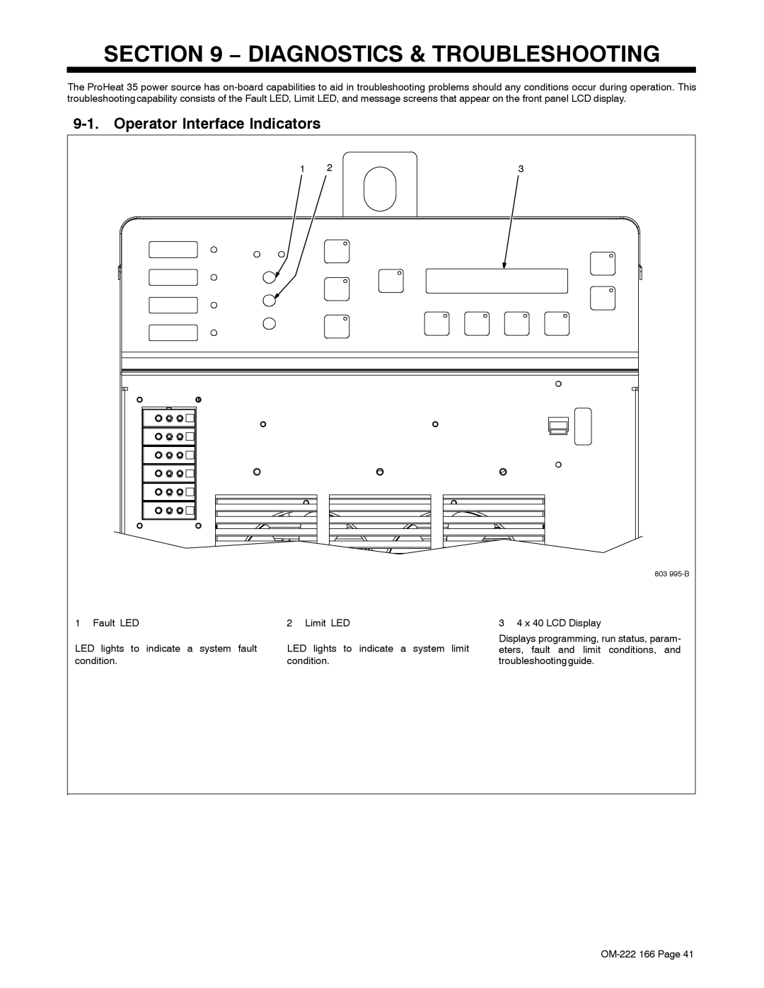
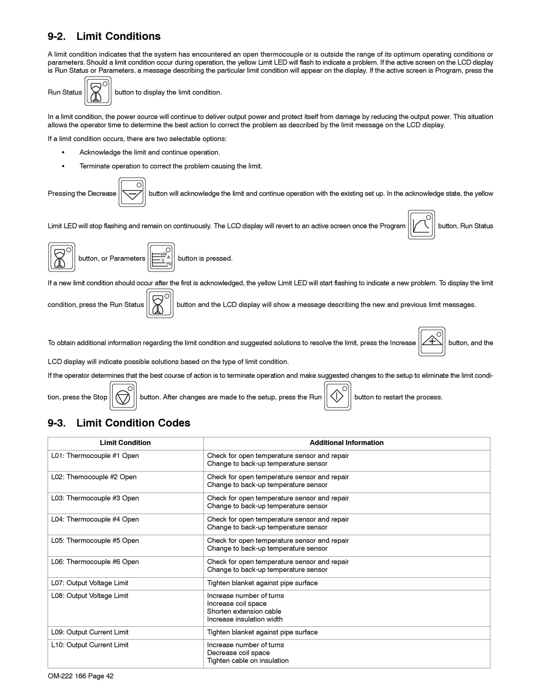
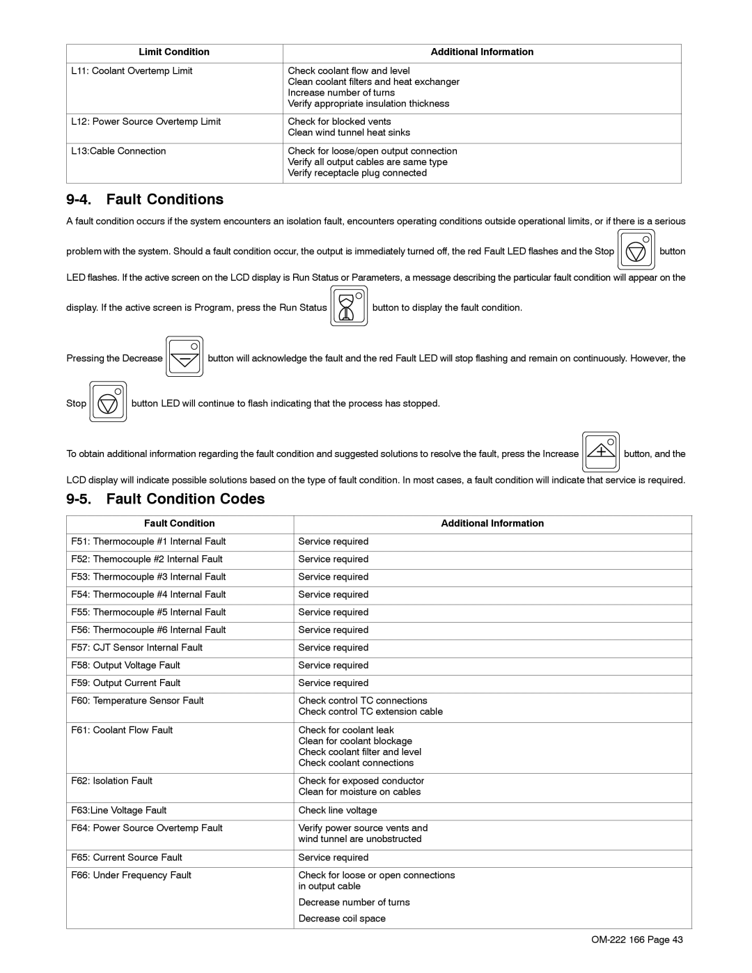
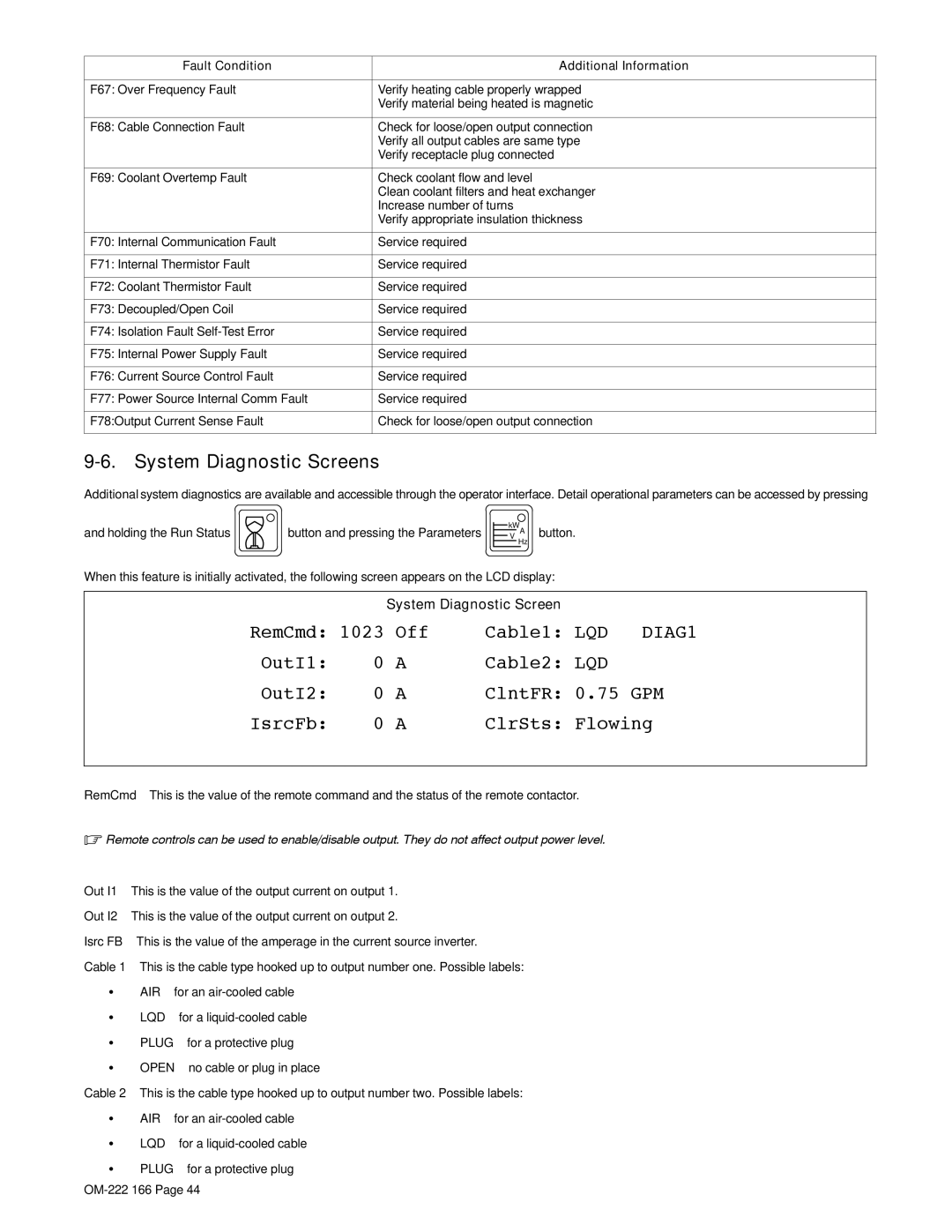
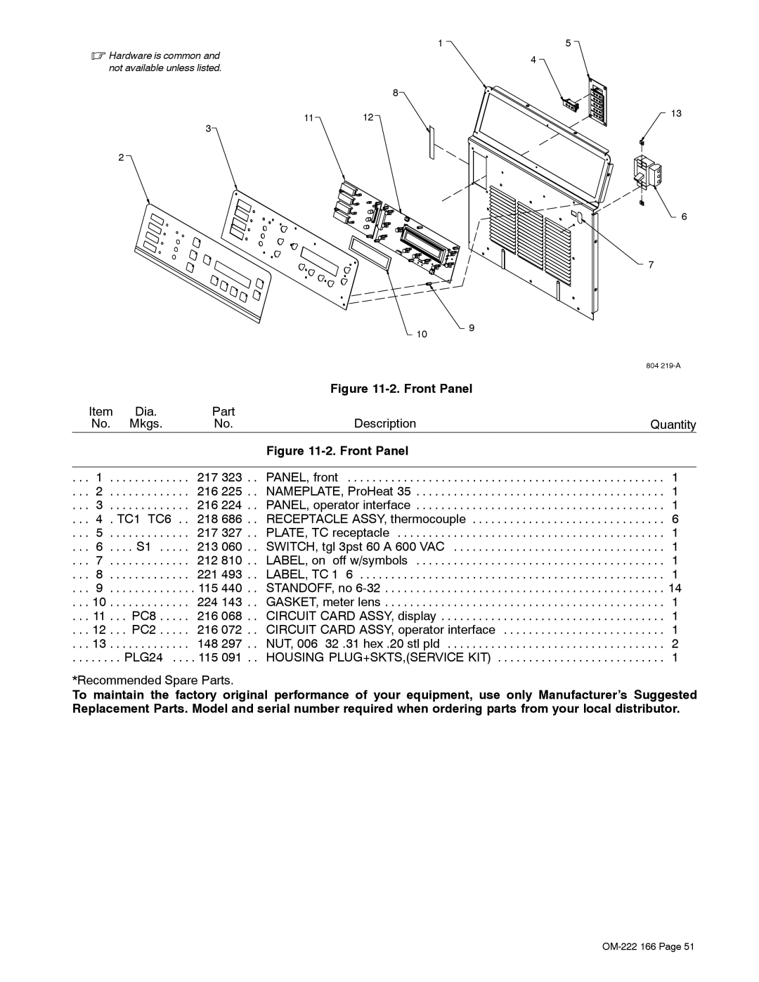
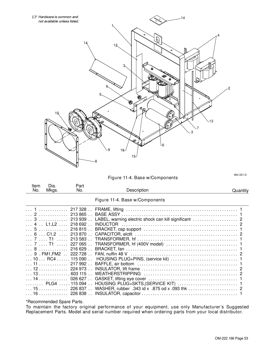
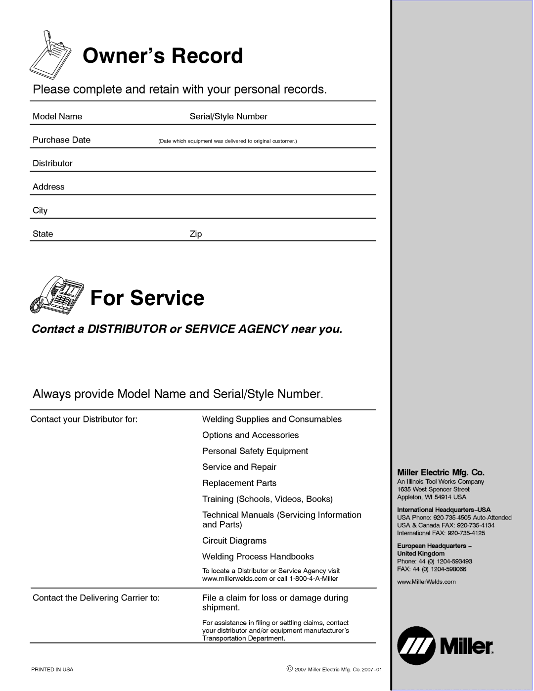
Miller Electric ProHeat 35 manual Front Panel

Page 57

. Hardware is common and

1

5


4

not available unless listed.


8


11

12

13


3


2


6

7


10

9


804 219-A


Figure 11-2. Front Panel


Item

Dia.

Part


No.

Mkgs.

No.

Description


Quantity


Figure 11-2. Front Panel


. . .

1

. .

. . . . . . . . . . .

217 323 . .

PANEL, front

. . . . . . . . . . . . . . . . . . . . . . . . . . . . .

. . . 1

. . . 2

. .

. . . . . . . . . . .

216 225 . .

NAMEPLATE, ProHeat 35

. . . . . . . . . . . . . . . . . . . . . . . . . . . . .

. . . 1

. . .

3

. .

. . . . . . . . . . .

216 224 . .

PANEL, operator interface

. . . . . . . . . . . . . . . . . . . . . . . . . . . . .

. . . 1

. . . 4

. TC1−TC6 . .

218 686 . .

RECEPTACLE ASSY, thermocouple

. . . . . . . . . . . . . . . . . . . . . . . . . . . .

. . . 6

. . .

5

. .

. . . . . . . . . . .

217 327 . .

PLATE, TC receptacle

. . . . . . . . . . . . . . . . . . . . . . . . . . . . .

. . . 1

. . .

6

. . . . S1

213 060 . .

SWITCH, tgl 3pst 60 A 600 VAC . .

. . . . . . . . . . . . . . . . . . . . . . . . . . . . .

. . . 1

. . .

7

. .

. . . . . . . . . . .

212 810 . .

LABEL, on−off w/symbols

. . . . . . . . . . . . . . . . . . . . . . . . . . . . .

. . . 1

. . .

8

. .

. . . . . . . . . . .

221 493 . .

LABEL, TC 1−6

. . . . . . . . . . . . . . . . . . . . . . . . . . . . .

. . . 1

. . .

9

. .

. . . . . . . . . . . .

115 440 . .

STANDOFF, no 6-32

. . . . . . . . . . . . . . . . . . . . . . . . . . . . .

. . . 14

. . . 10

. .

. . . . . . . . . . .

224 143 . .

GASKET, meter lens

. . . . . . . . . . . . . . . . . . . . . . . . . . . . .

. . . 1

. . . 11

. .

. PC8

216 068 . .

CIRCUIT CARD ASSY, display . . . .

. . . . . . . . . . . . . . . . . . . . . . . . . . . . .

. . . 1

. . . 12

. .

. PC2

216 072 . .

CIRCUIT CARD ASSY, operator interface

. . . 1

. . . 13

. .

. . . . . . . . . . .

148 297 . .

NUT, 006−32 .31 hex .20 stl pld . . .

. . . . . . . . . . . . . . . . . . . . . . . . . . . . .

. . . 2

. . . . . .

. .

PLG24 . . . . 115 091 . .

HOUSING PLUG+SKTS,(SERVICE KIT)

. . . 1

*Recommended Spare Parts.

To maintain the factory original performance of your equipment, use only Manufacturer’s Suggested Replacement Parts. Model and serial number required when ordering parts from your local distributor.

OM-222 166 Page 51

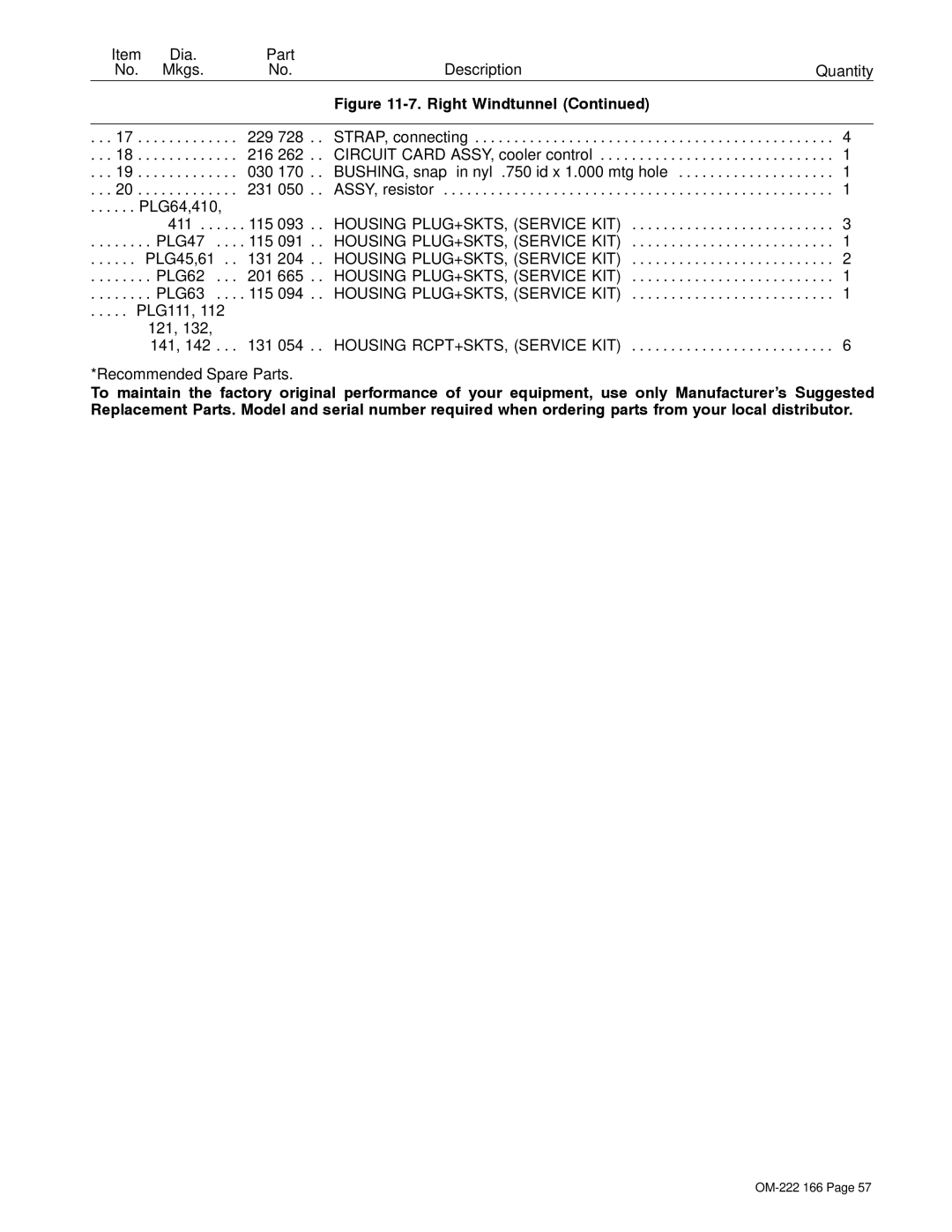
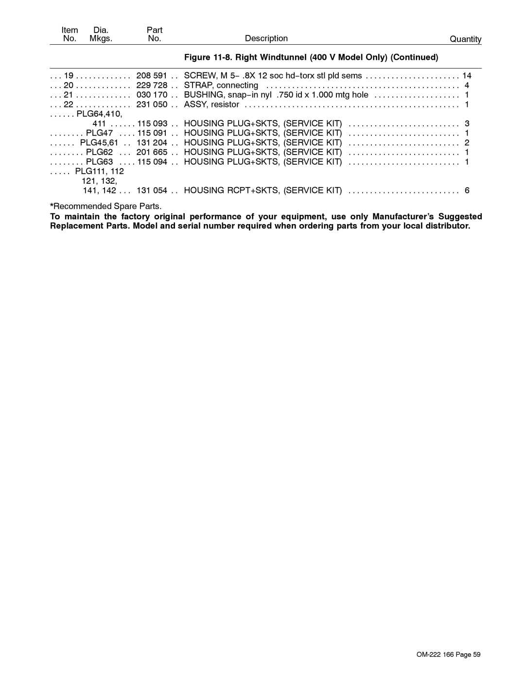
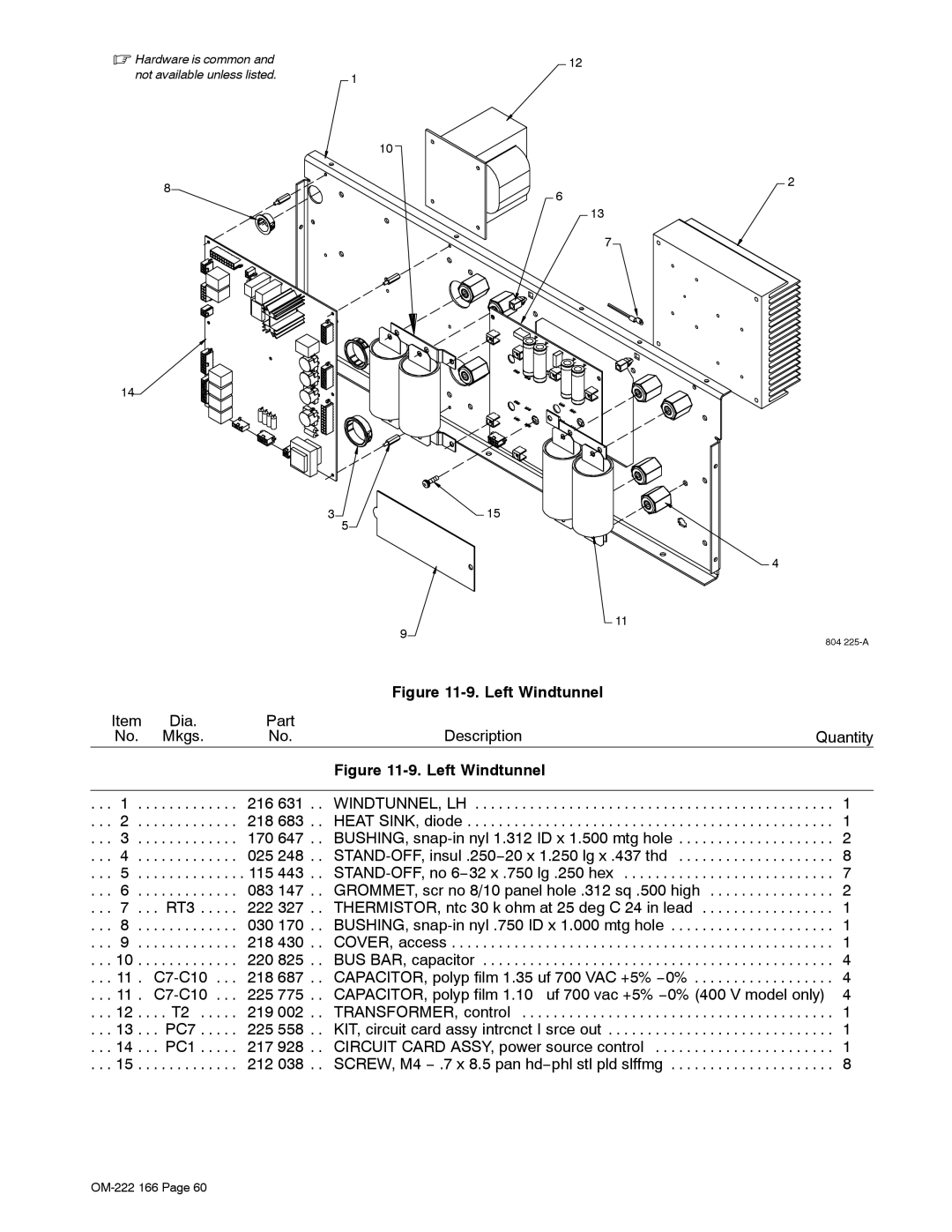
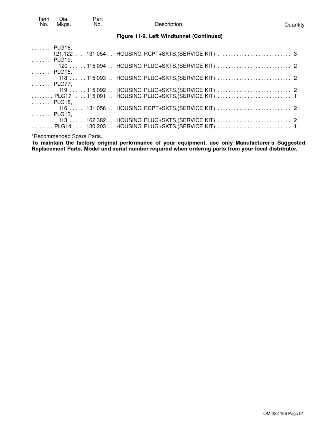
Image 57
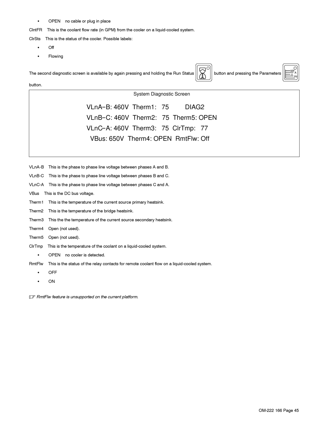
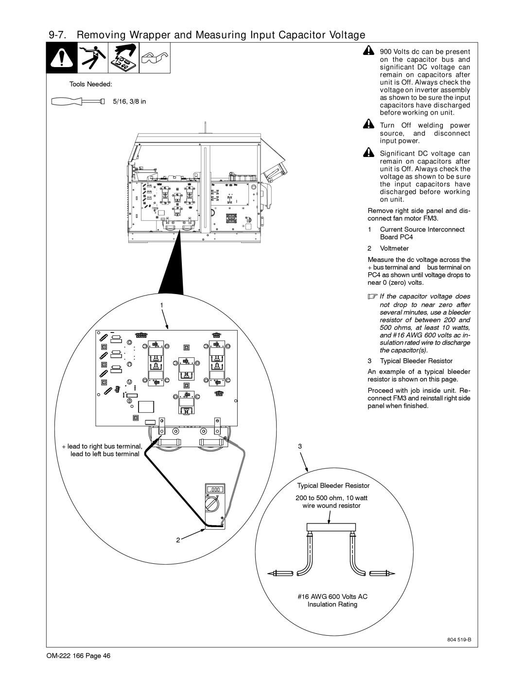
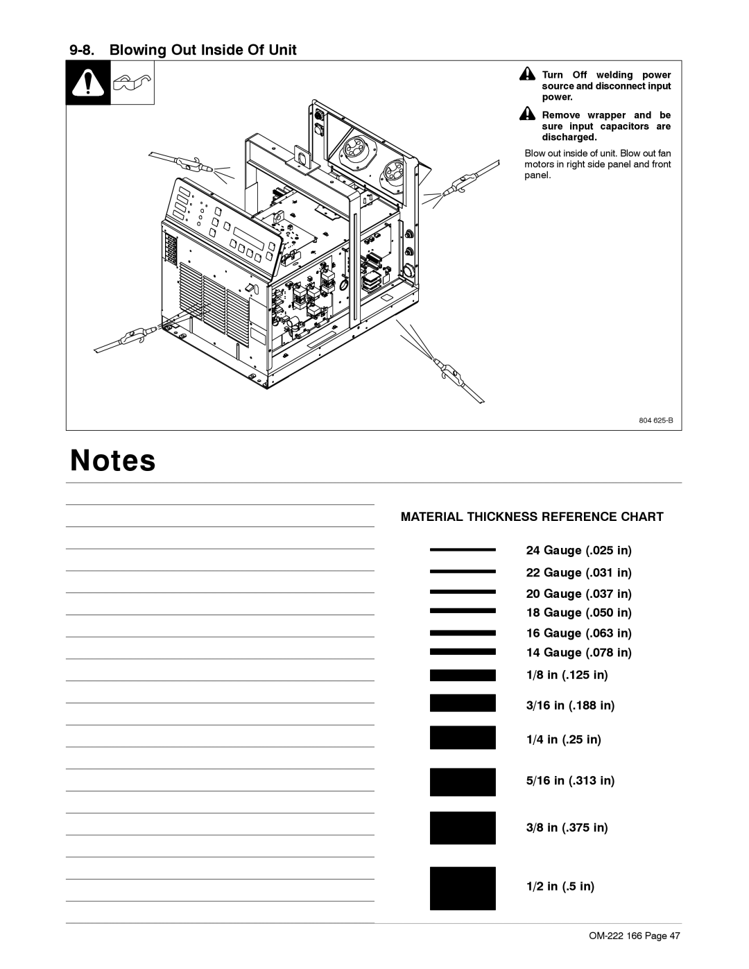
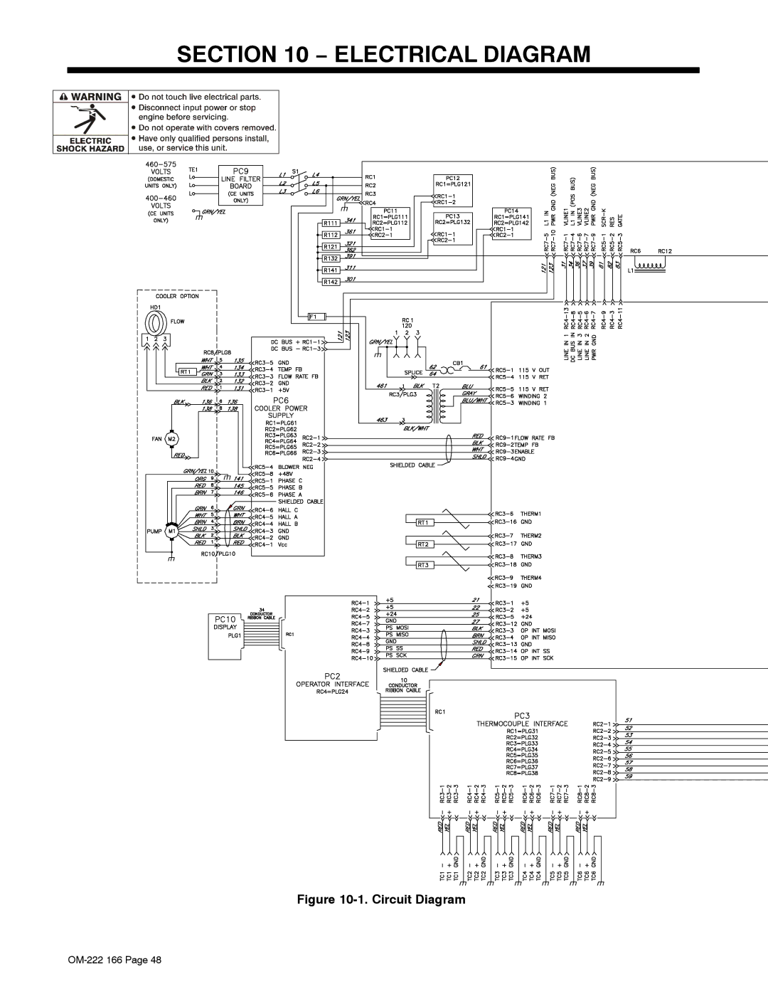
Contents OM-222 166K 2007−11 Processes DescriptionFile Induction Heating From Miller to You Table of Contents Routine Maintenance Blowing Out Inside Of Unit − MaintenanceLimit Conditions Limit Condition Codes Fault Conditions EMF InformationDirectives StandardsDecstat1/07 Page Induction Heating Hazards Symbol UsageElectric Shock can kill Fumes and Gases can be hazardousCalifornia Proposition 65 Warnings About Implanted Medical Devices Principal Safety Standards EMF Information− Consignes DE Sécurité − Lire Avant Utilisation Signification des symbolesUNE Décharge Électrique peut entraîner la mort LES Fumées ET LES GAZ peuvent être dangereuxLE Chauffage PAR Induction peut provoquer des brûlures Risque D’INCENDIE OU D’EXPLOLA Chute DE L’APPAREIL peut blesser DES Organes Mobiles peuvent provoquer des blessuresProposition californienne 65 Avertissements Principales normes de sécurité Information EMFEn ce qui concerne les implants médicaux − Definitions Power before working on Shown by the symbolsAre possible hazards as KillWeee Label For Products Sold Within The EU Rating Label For CE ProductsSymbols And Definitions − InstallationSpecifications I1maxSelecting a Location Do not move or operate unit where it could tipTipping Movement Location And AirflowPhase Input Voltage Electrical Service Guide50 Hz Three Min Grounding Conductor Size In AWGWelding Power Source Input Power Connections Connecting 3-Phase Input Power For 460/575 Volt ModelsDisconnect Device Input Power Connections GND/PE Earth GroundConnecting 3-Phase Input Power For 400/460 Volt Models Power Source Output Connections Remote 14 Receptacle RC14 Information and Connections Remote 14 Socket InformationSocket Socket Information Signal Common Temperature Recorder Socket InformationSocket No Socket Information UnusedReceptacles Plug Secondary Insulation ProtectionHandle Magnet Workpiece Use handle to place magnet on the workpieceLocating Thermocouples Volt AC Duplex Receptacle And Supplementary ProtectorOther end is fitted with a 2-pin type K connector Attaching Welded Thermocouples Do not weld thermocouples while connected to power sourcePlacing Temperature Probe Using Contact ThermocouplesControls − Components and ControlsSafety Equipment − Setup and OperationPower Source/System Setup System DescriptionOM-222 166 Mode....... Preheat Control TC Temperature Soak Time Temperature-Based ControlDecrease button to change the value to the desired setting ProgrammingPwht Post-Weld Heat Treat Bake-OutCustom Program Soak ParametersEnd Custom ProgramType.......Step 600Number OM-222 166 Ramp Temperature 600 Ramp Rate 600 /HrSoak Function SoakNumber End FunctionManual Control Typical 5-Segment Custom ProgramSoak at 1250 degrees F for a period Run Status Temperature Based ControlTC5 Target Temp −−−− TC6 Countdown.. −−−−−− Preheat, Bake-Out And Pwht Run Status ScreenParameters Power TC5 Current TC6 Voltage Frequency KHzCooler Cooler cannot be turned off while output is onMust be running to enter Hold mode Real-Time OperationProgram run is initiated, the Run Button. a change of program parameters Power Source Output Characteristics System Operating CharacteristicsAir Cooled Output Liquid Cooled OutputRoutine Maintenance − MaintenanceDisconnect power Before maintainingServicing Hazards − Safety Precautions for ServicingCalifornia Proposition 65 Warnings Operator Interface Indicators − Diagnostics & TroubleshootingLimit Condition Codes Limit ConditionsRun Status Limit Condition Additional InformationFault Conditions Fault Condition CodesFault Condition Additional Information System Diagnostic Screens Off Cable1 LQD DIAG1 OutI1 Cable2 LQD OutI2 ClntFR 0.75 GPMClrSts Flowing Therm2 Therm1Therm3 VBusTurn Off welding power source, and disconnect input power Removing Wrapper and Measuring Input Capacitor VoltageTools Needed 16, 3/8 Blowing Out Inside Of Unit Material Thickness Reference ChartCircuit Diagram − Electrical Diagram218 057-G See Figure 11-313 11-2 − Parts ListFront Panel Rear Panel Base w/Components Top Windtunnel Capacitor Assembly Right Windtunnel 229 Right Windtunnel 400 V Model Only 208 Left Windtunnel PLG14 10. Hermaphroditic Blank Plug Assy SOCKET/WRENCH Selection Table Standard Metric OM-222 166 Service Your distributor also givesSupport Miller Electric Mfg. Co To locate a Distributor or Service Agency visitFor assistance in filing or settling claims, contact Your distributor and/or equipment manufacturer’s