Installation and Setup (Continued)
ELECTRICALCONNECTIONANDCONTROLS
The electrical control box (with circuit breaker) and "On/Off" switch are located on the left side of the machine frame. See Figure
Use of an extension cord is not recommended. However, if one is needed for temporary use, it must have a wire size of 1.5 mm diameter [AWG 16 ], have a maximum length of 30.5 m [100 ft], and must be properly grounded.
![]() WARNING
WARNING
•To reduce the risk associated with hazardous voltage:
−Position electrical cord away from foot and vehicle traffic.
Note: Machines outside the U.S. may be equipped with 220/240 Volt, 50 Hz systems or other electrical requirements compatible with local practice.
SPACE REQUIREMENTS
The left side of the machine must be a minimum of 1.0 m (39.4 inches) from the nearest wall.
The right side of the machine must be a minimum of 0.7 m (27.6 inches) from the nearest wall.
The machine requires a minimum of 2.7 m (106.3 inches) height.
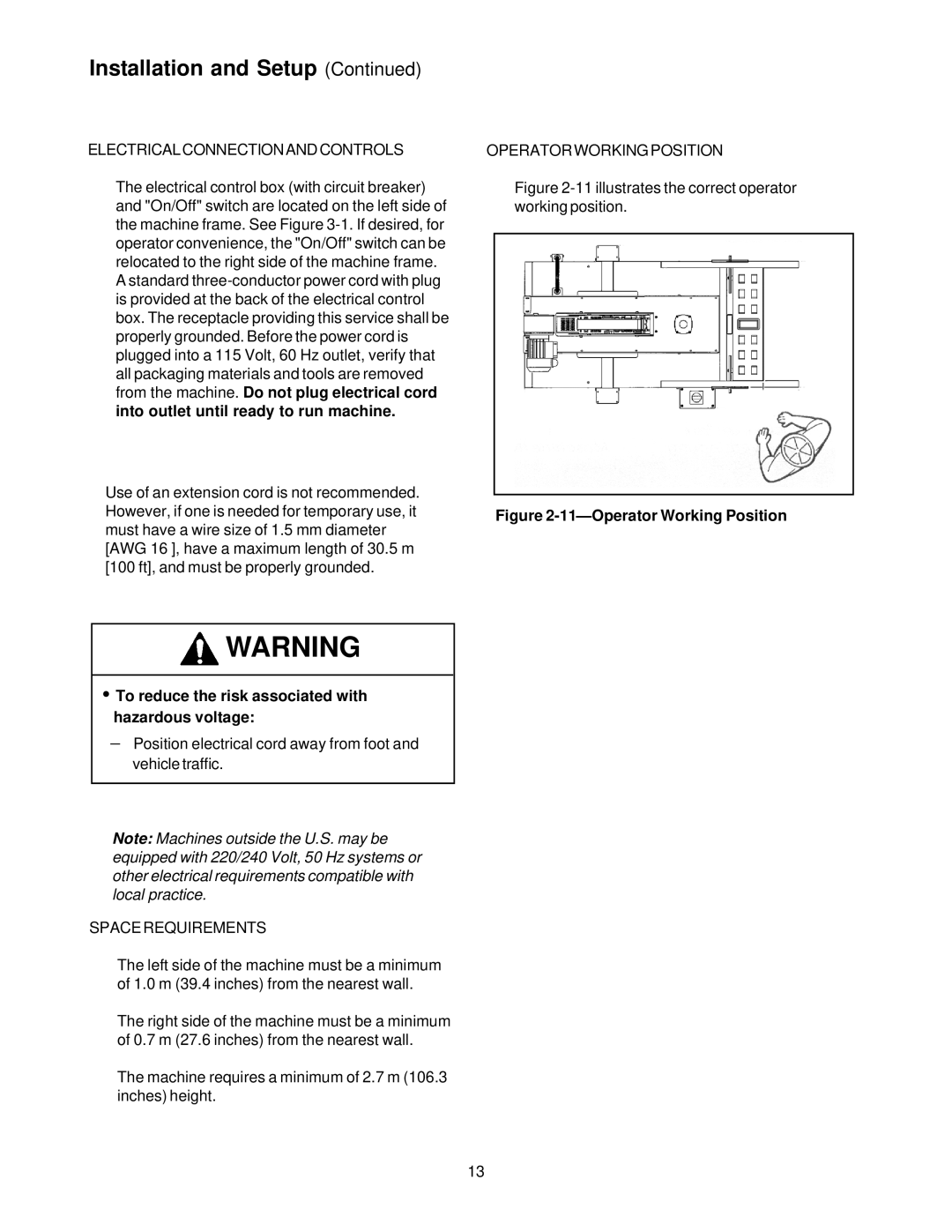
OPERATOR WORKING POSITION
Figure 2-11 illustrates the correct operator working position.
Figure 2-11—Operator Working Position
13