9
Item | Icon | Component | Item | Icon | Component |
|
|
|
|
|
|
F2 | LAN1 and LAN2 | J | |||
|
| status indicator |
|
|
|
|
|
|
| ||
F3 | Status/fault | K | |||
|
| indicator |
|
| activity indicator |
|
|
|
| ||
F4 | Power indicator | L | |||
|
|
|
|
| carrier latch |
|
|
|
|
| |
F5 | System ID |
|
|
| |
|
| indicator |
|
|
|
* The
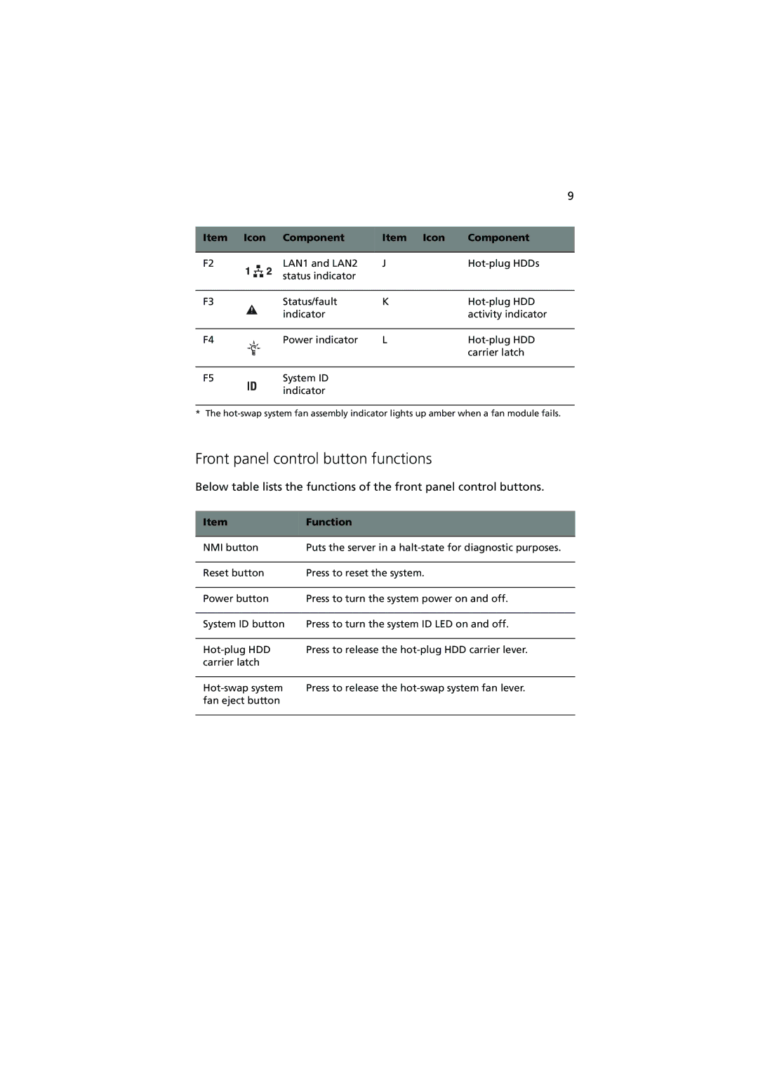
Front panel control button functions
Below table lists the functions of the front panel control buttons.
Item | Function |
|
|
NMI button | Puts the server in a |
|
|
Reset button | Press to reset the system. |
|
|
Power button | Press to turn the system power on and off. |
|
|
System ID button | Press to turn the system ID LED on and off. |
|
|
Press to release the | |
carrier latch |
|
|
|
Press to release the | |
fan eject button |
|
|
|
