ESU 120e
Part Number 1200420L1-1
Trademarks
Adtran Web Site Product Matrix Faxback Document Line
Y2K Project Line
Mail
Page
Canadian Emissions Requirements
Canadian Equipment Limitations
Vii
Important Safety Instructions
Warranty and Customer Service
Page
Table of Contents
Chapter Operation
Snmp
Chapter Status Menu
Chapter Configuration Menu
Chapter Utility Menu
Chapter Test Menu
Local Loopbck Remote Loopbck Test Pattern
Pattern Result
Loopbk
DIS 511 Reslt
Telnet/Terminal Menus
Appendix A. Understanding Snmp
Index-1
Xvi 61200420L1-1
List of Figures
List of Figures
List of Tables
List of Tables
Introduction
ESU 120E Overview
ESU 120e Features
ESU Option Modules
ESU 120E Configuration Applications
Option Module Architecture
Router, PBX Application
Introduction
UNPACK, INSPECT, Power UP
Receipt Inspection
AD Tran Shipments Include
Customer Provides
Power Connection
Ground ING Instructions
Installation
ID Entification of Rear Panel Layout
ESU 120e Rear Panel
ESU120E Interfaces
Network Interfaces
Network Test Interface
Nx56/ 64 Serial Interface
POWER-UP Testing
Self-Test
Initialization
Board-level tests
Unit-level tests
Set User Passcode
Set Control Port
Chain In PC
Chain In/ Chain Out
Normal POWER-UP Proced URE
Installation
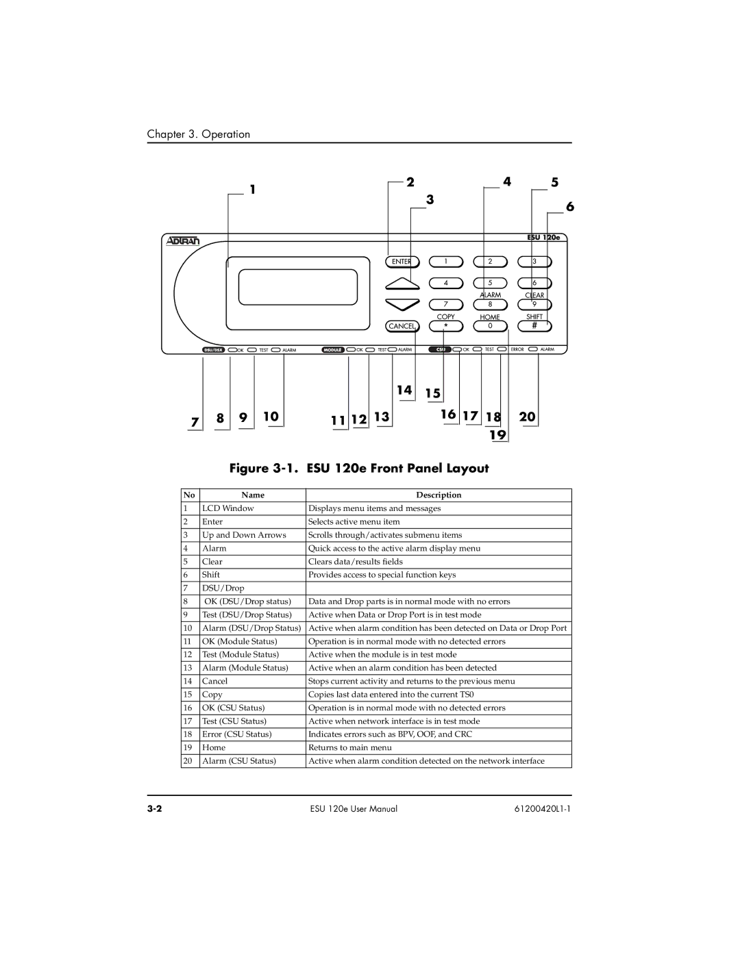
Peration
Front Panel
11 12 16 17
ESU 120e Front Panel Layout
LED D escriptions
CSU Status
SU/ D rop Status
Operation keys
Module Status
General Menu Operation
Select and Activate a Menu Item
NI Perf Rpts NI Errors
4VIEW History END of List
Port Status Remote Port Clear Port ALM Enet Status
Ata Port Identification
Front Panel Menu Structure
Exit Any Menu Field Operation Or D isplay
Alternate Methods of Control
Watch PRO AD Tran PC Program
Step Action
Terminal Mode
Telnet
Status Menu
Network Interface Performance Reports NI Perf Rpts
Network Interface Performance Report
Network Interface Errors NI Errors
Active Alarms
D isplay of Alarm Messages
View History
Port Status
Nx56/ 64 Menu Items D TE D ata/ CK
TE Status
Port Rate
Clear Port Alarm
Rop Menu Items D SX Errors
Remote Port
Enet Status
Configuration Menu
Configuration Menu Tree
Network NI
Network NI Menu Items
Menu Item Description
Intface
From the NI. See ESU 120 Clock Sources on page 5-5 for more
ESU 120e Clock Sources
Network Timed
Network Timed Clock Source
Base D rop Timed
D rop Timed Clock Source
Base D TE Timed
Internal Timing
Internal Clock Source
Normal CSU Timing
Normal CSU
Unit Menu
May not be used as a terminal interface
Slip
Map Exchange Map Xchng
Map In Use AB
OFF
TS0 Map a and TS0 Map B
D S0 Map D esignations
Copy a Temp
Create Temp
Idle
Review MAP
Review Temp
Edit Temp
Apply Temp a
Port Configuration Port Config
Nx56/ 64 Port Configuration Port Config Menu Items
Data
CTS
DCD
DSR
Normal Mode of Operation
Rop Port Configuration Port Config Menu Items
Configuration Menu
Utility Menu
Factory Restore
Time/ D ate
Set Passcode
Enter Passcode from Other Menus
Special Feature
Change/ Set a Passcode
No Passcode D esired
Unit ID
Software Revision Software Rev
To Set the Unit Identification
No Unit ID D esired
CMD Mode
Port Utility
Enet Address
Utility Menu
Test Menu
Network Tests
Loopback Tests
Network Interface Loopbacks
Line On Activates the line loopback
BCK
All Ones
All Zeros
Qrss Pattern
Qrss always runs at 64K/TS0
BES
SES
Sync
Run Self-Test
Port Tests
Test Name What it does
Port Test Menu Items for 0.1 Nx56
PRT/LCL
Remote
Patt
Cancel Tests
Port Test Menu Items for 0.2 D rop Loopback
Test Menu
Main Menu
Telnet/ Terminal Main Menu
Status, Config, Util, and Test Menu Options
TS0 Maps Configuration Menu
Initializing the Temp Map
Editing the Temp Map
Applying the Temp Map
Reviewing Temp Maps
Remote Menu Access
Management Configuration
Snmp Read Community
Snmp Read/ Write Community
Snmp Trap Community
Telnet/ Terminal Timeout
Telnet/ Terminal Password
Auth. Fail Traps Sent
Poll Link Status Traps Sent
Flash D ownload
Quit Session
Telnet/Terminal Menus
Snmp Basic Components
Network Manager
Agent
Command S
MIB
GetRequest
GetNextRequest
ESU 120E Snmp Access
Messages
GetResponse
Trap
Snmp Trap Configuration
Snmp MIB Browser Configuration
Snmp MIB Files
Ppendix a . Understanding Snmp
Wiring
Network interface Connector
Connector type 15-pin female D connector
Table B-1. Network Pinouts
Connector type RJ-48 Part Number AMP#
Control In/ Chain
Table B-2. Control In/ Chain-in Pinout
Pin Name Description
Table B-3. Chain-Out Connector Pinout
Chain Out
Connections
Connector type Pin female D connector
Ata Port Interface
Table B-4. Nx56/ 64 Pin Assignments for EIA-530
Pin
Table B-5. Nx56/ 64 Pin Assignments for V.35 Mode
Ccitt
Table B-6. Adapter Cable, D B 25 to V.35, 34-Pin Winchester
1200285L1 DB25P Pin 34 Pin Name
Table B-7. Nx56/ 64 Pin Assignments for V.11/ x.21 Mode
Pin Name Description Source
Table B-8. Adapter Cable D B25 to X.21, D B15 Connector
Table B-9. Pinout Connectors for Terminal Interface
Base D rop PBX
Name DB25Pin DA15S Pin
Connector type Shielded RJ48 USOCPart Number AMP #
10BaseT
Table B-10 BaseT Pinout
Pin Name To Nic
Ppendix B. Connector Pinouts
Alarm Messages
Network Interface NI
Nx56/ 64 Interface
Rop Port Interface
Status Messages
Network Interface NI
Nx56/ 64 Interface
Electrical Specifications
Network Interface
CRC-4, FAS,CAS
HDB3
Nx56/ 64 D rop Port Interface
Nx56/ 64 V.35 Interface
CTS, DCD, DSR
Rop Port Interface
Management Interfaces
Chain In/ Out Ports
Watch
Option Slot Interface
Chassis Specifications
Environmental Specifications
Index
NI Errors
Snmptrap Configuration A-4
Index-4
Presales Inquiries and Applications Support
Post-Sale Support
Repair and Return