Agilent Technologies Model N3280A Component Test DC Source
USER’S Guide
Certification
Warranty Information
General
Safety Summary
Safety Symbols
Declaration
Printing History
Acoustic Noise Information
Table of Contents
Scpi Command Completion Using Device Clear
Types of Scpi Commands
External References
Gpib Capabilities of the DC Source Introduction to Scpi
Measurement Commands
Scpi Programming Commands At a Glance Calibration Commands
Output Commands
Status Commands
Trigger Commands
System Commands
Common Commands
Voltage Priority Tests
Error Number List 103
Ripple and Noise Tests
Transient Response Tests
Page
Document Orientation
Safety Considerations
Description
Options and Accessories
Remote Programming
Option Description
Voltage Priority Operation
Output Characteristics
Current Priority Operation
Output Characteristic Current Priority
Measurement Characteristics
Start of a Measurement
Inspection
Cleaning
Damage Packaging Material
Additional Items
Bench Operation
Location
Rack Mounting
Do not block the fan exhaust at the rear of the unit
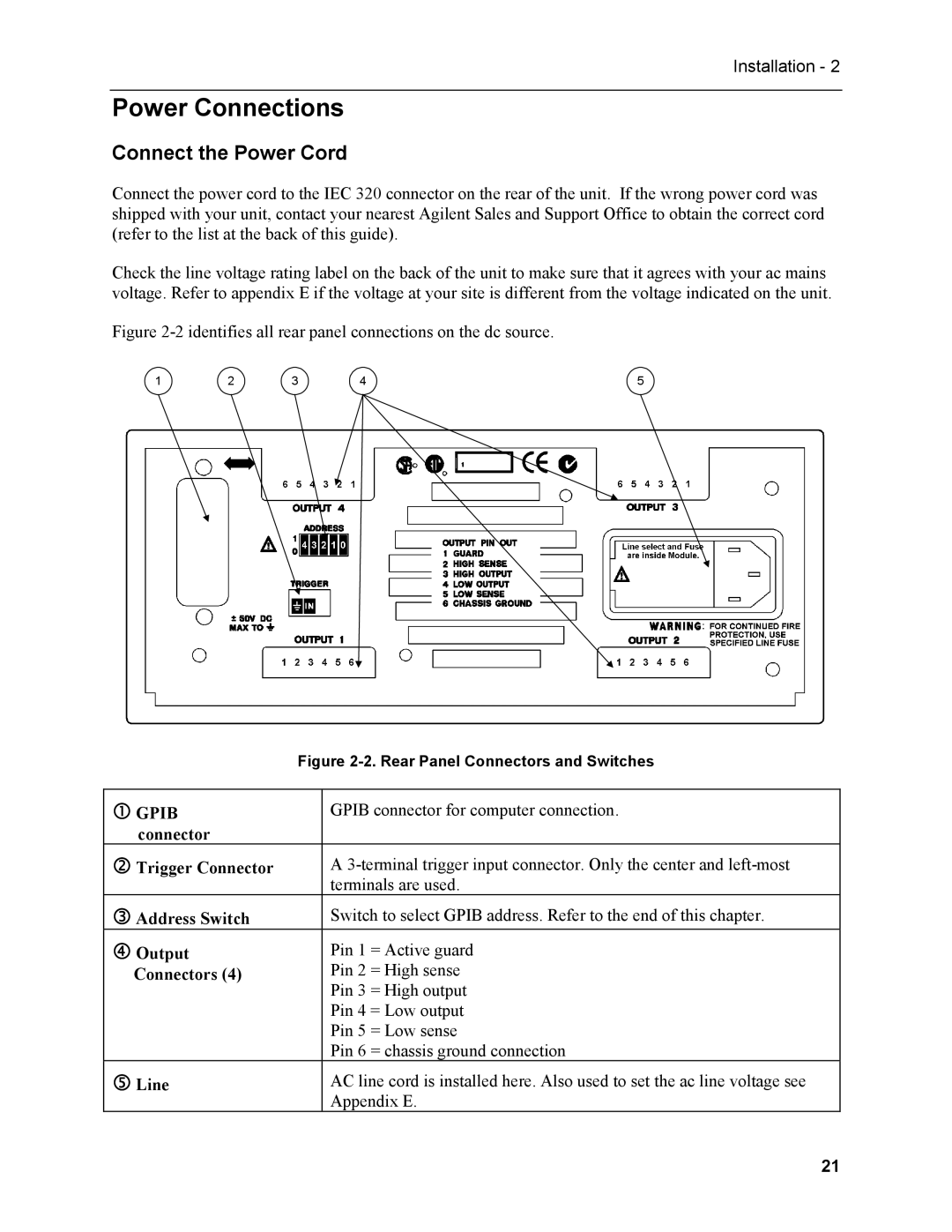
Connect the Power Cord
Power Connections
Turn the unit off before connecting any wires
Output Connections
Outputs 1
Voltage Drops and Lead Resistance
Current Ratings
Ampacity and Resistance of Stranded Copper Conductors
AWG No Maximum Ampacity Resistance at 20 deg. C Free air
Guard Connections for Test Fixtures
Coaxial Guard Connections
Computer Connections
External Trigger Connections
Maintaining Stability
OVP Considerations
Switch Setting
Settings for Power Module Configuration Switch
Switch Setting Address
Gpib Address
Front Panel Description
Checkout Procedure
Procedure
Explanation
Runtime Error Messages
Selftest Error Messages
Power-On Selftest Errors
Case of Trouble
Page
Gpib Capabilities of the DC Source
External References
Gpib References
Scpi References
Types of Scpi Commands
Introduction to Scpi
Conventions Used in This Guide
Including Common Commands
Multiple Commands in a Message
Using Queries
Moving Among Subsystems
Types of Scpi Messages
Message Unit
Channel List Parameter
Scpi Data Formats
Suffixes and Multipliers
Scpi Command Completion
Response Data Types
Class Suffix Unit Unit with Multiplier
Outputstate Example
Using Device Clear
Page
Introduction
Power-on Initialization
Programming the Output
Enabling the Output
Output Mode
Overvoltage Protection
Output Current
Triggering Output Changes
Oscillation Protection
Output Trigger Model
Setting the Voltage and Current Trigger Levels
Enabling the Output Trigger System
Selecting the Output Trigger Source
Making Measurements
Generating Output Triggers
Average Measurements
Measurement Samples and Time Interval
Power Line Cycles
Current Ranges
Triggered Measurements
Window Functions
Returning All Measurement Data From the Data Buffer
Measurement Trigger Model
Enabling the Measurement Trigger System
Selecting the Measurement Trigger Source
Output Settling Delay
Selecting the Sensing Function
Generating Measurement Triggers
Pre-trigger and Post-trigger Acquisition
Pre-trigger and Post-trigger Data Acquisition
DC Source Status Model
Programming the Status Registers
Operation Status Group
Bit Configurations of Status Registers
Standard Event Status Group
Questionable Status Group
Status Byte Register
MSS and RQS Bits
Servicing Operation Status and Questionable Status Events
Determining the Cause of a Service Interrupt
Subsystem Commands
Common Commands
Programming Parameters
Scpi Programming Commands At a Glance
Subsystem Commands Syntax
Save new cal constants in non-volatile memory
FUNCtion Mode mode, @list VOLTage
Mode mode, @list DELay
Sets the output voltage in voltage priority mode
Sets the triggered output voltage in voltage priority mode
ESE n
Common Commands Syntax
SRE n
Output Programming Parameters
CALibrateCURRent
Calibration Commands
CALibrateCURRentLIMitPOSitive CALibrateCURRentLIMitNEGative
CALibrateCURRentMEASure
CALibrateDATA
CALibratePASSword
CALibrateDATE
CALibrateLEVel
CALibrateSAVE
CALibrateSTATe
CALibrateVOLTage
FETChARRayCURRent? FETChARRayVOLTage?
Measurement Commands
FETChCURRent? FETChVOLTage?
Query Syntax
MEASureCURRent? MEASureVOLTage?
MEASureARRayCURRent? MEASureARRayVOLTage?
SENSeCURRentRANGe
Enter values greater than 0.015A
SENSeSWEepNPLCycles
SENSeFUNCtion
SENSeSWEepOFFSetPOINts
Query Syntax SENSeFUNCtion? @channel list
SENSeSWEepPOINts
SENSeSWEepTINTerval
SENSeWINDow
OUTPut
Output Commands
OUTPutOSCProtect
OUTPutPROTectionCLEar
SOURceCURRentIMMediate SOURceCURRentTRIGgered
Default Suffix
SOURceCURRentLIMitIMMediate SOURceCURRentLIMitTRIGgered
SOURceCURRentLIMitBWIDth
SOURceDELay
SOURceDELayMODE
SOURceCURRentMODE SOURceCURRentLIMitMODE
SOURceVOLTageALCBWIDth
SOURceFUNCtionMODE
SOURceVOLTageIMMediate SOURceVOLTageTRIGgered
Query Syntax SOURceFUNCMODE? @channel list
SOURceVOLTagePROTectionSTATe
SOURceVOLTageMODE
Query Syntax SOURceVOLTagePROTectionSTATe? @channel list
NR10 or
STATusOPERationENABle
Status Commands
Bit Configuration of Operation Status Registers
STATusOPERationEVENt?
Parameters Preset Value
STATusPRESet
Command Syntax STATusPRESet Parameters None Examples
STATusOPERationNTR STATusOPERationPTR
Query Syntax STATusQUEStionableENABle? @channel list
STATusQUEStionableENABle
STATusQUEStionableCONDition?
STATusQUEStionableNTR STATusQUEStionablePTR
System Commands
SYSTemERRor?
SYSTemVERSion?
ABORt
Trigger Commands
INITiateNAME
TRIGgerACQuire
TRIGgerTRANsientSOURce
TRIGgerACQuireSOURce
TRIGgerTRANsient
RST Value
Command Syntax *CLS Parameters None
Common Commands
Parameters Power-On Value Examples
Bit Configuration of Standard Event Status Enable Register
Field Information
Example
Query Syntax *OPT? Returned Parameters Aard
RST Settings
Power-on Value
Query Syntax TST? Returned Parameters NR1
Bit Configuration of Status Byte Register
Table A-1. Specifications
Table A-2 Supplemental Characteristics
Safety
Output Common Mode
Dimensions
Weight
Figure A-1. Output Impedance Graphs all outputs
Equipment Required
Measurement Techniques
Performance & Verification Tests
Test Setup
Electronic Load
Programming
Voltage Priority Tests
Program Commands
Voltage Programming and Readback Accuracy
Positive Current Limit +CL
Negative Current Limit -CL
Action Program Commands
Current Programming and Readback Accuracy
Current Priority Tests
Voltage Priority, Constant Voltage Load Effect
Load Effect Tests
Voltage Priority, -Current Limit Load Effect Test
Voltage Priority, +Current Limit Load Effect
Source Effect Tests
Current Priority Constant Current Test
Voltage Priority, Constant Voltage Source Effect
Voltage Priority, -Current Limit Source Effect
Voltage Priority, +Current Limit Source Effect
Current Priority, Constant Current Source Effect
Voltage Priority Ripple and Noise
Ripple and Noise Tests
Voltage Priority, Transient Recovery Time
Transient Response Tests
Current Priority Ripple and Noise
Figure B-2. Transient Waveform Voltage Priority
Current Priority Transient Recovery Time
Figure B-3. Transient Waveform Current Priority
Performance Test Equipment Form
Performance Test Record Form
Enable Calibration Mode
Performing the Calibration Procedure
Positive Current Limit Calibration
Negative Current Limit Calibration
5A Range Current Measurement Calibration
100
15mA Range Current Measurement Calibration
Saving the Calibration Constants
101
Calibration Error Messages
Changing the Calibration Password
Table B-3. Gpib Calibration Error Messages
Error Meaning
Error Number List
Table C-1. Error Numbers
103
104
Error Messages
105
Error Messages C
Page
107
Line Voltage Selection
Page
Mating Connector Part Numbers
Earlier Version Output Connectors
Rear Panel Pinout Assignments
CHG-2010-J01010-KEP
Page
111
Index
112
Index
Scpi
113
114
Canada Australia/New Zealand
United States Latin America
Europe Asia Pacific
Japan
Manual Updates