MAX-CSE/MAX-CSD10
AMX Limited Warranty and Disclaimer
Table of Contents
MAX-CSD10 Web Interface
Displaying Stream Content
Page
MAX-CSE Video Encoder
MAX Encoder Features
Overview
MAX-CSE Product Specifications
MAX-CSE Specifications
While in IR mode
Sensing for IR ports
MAX-CSD10 Video Decoder
MAX-CSD10 Product Specifications
MAX Decoder Features
MAX-CSD10 FG2178-72
MAX-CSD10 FG2178-72 Specifications
AAC
MAX-CSD10 Specifications
Composite OUT
Page
Wiring Guidelines Direct Power
MAX-CSE and MAX-CSD10 Installation
MAX-CSE and MAX-CSD10 Connections and Wiring
Port Assignments and Functionality
Wiring a Power Connection
Wiring Length Guidelines
Preparing Captive Wires
Wiring Guidelines Indirect Power via PoE
PoE Special Wiring Instructions
MAX-CSE
Wiring the MAX-CSE Connectors and Cables
VDC power Supply
Signals Connection Pairing Color
Ethernet/RJ-45 Port Connections and Wiring
Ethernet RJ-45 Pinouts and Signals
MIC
DB9 Device Port Connections and Wiring
Power over Ethernet PoE Wiring
Ethernet LEDs
Input/Output I/O Port Connections and Wiring
IR/Serial Port Connections and Wiring
RS-232/422/485 Device Port Wiring Specifications
Port Wiring Specifications
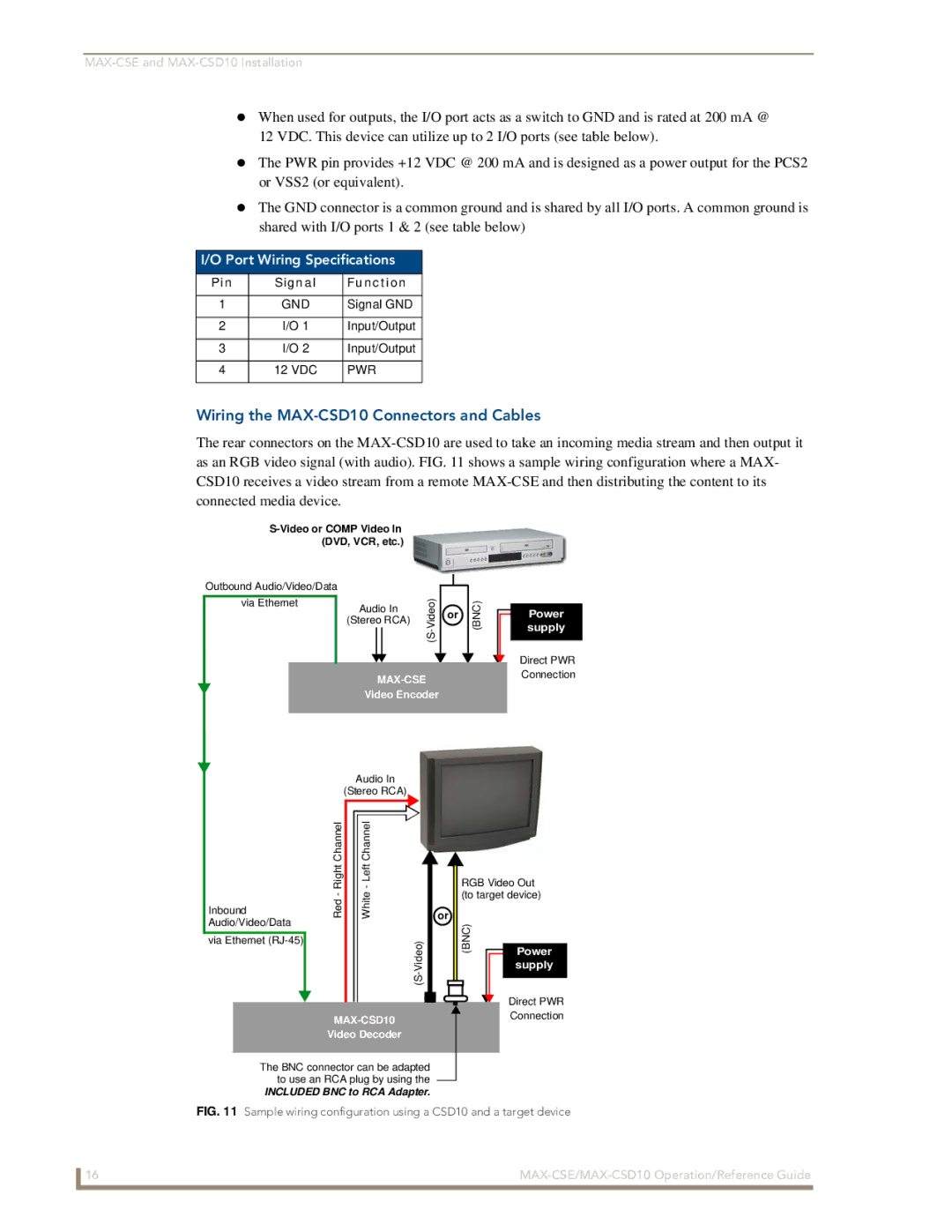
Wiring the MAX-CSD10 Connectors and Cables
Pin Signal Function
Installing Into an Equipment Rack
Page
Security Terms
Default Security Configuration
MAX-CSE Web Interface
Security Terms
Administrator account
Default Security Configuration case-sensitive
Communicating with the Unit via the Browser-Based UI
Feature Description Navigation Bar
MAX-CSE User Interface Overview and Features
User Interface Features
Browser-based UI Application Overview
Feature Description
Administration Page Features
Stream Status
Feature Description Resources
Administration
Administration
Example Computer Course
Mode
Changing the Program Description
Upload Firmware
Click Upload a File Click Reboot done. Upload a File
Upgrading New Firmware
Stream Profiles
Stream Profiles
Feature Description Encoder Profile
Stream Profiles Page Features
Video
30fps for Ntsc and 352x288 @ 24 fps for PAL
Audio
SVCD, MP3
Stream
SAP Settings
Obtaining the IP information for a target Modero
Encoder Profiles and Parameters
VCR
Set-up
Changing the Encoder Profile
Set up Page Features
Changing Video and Audio Settings
Feature Description Video
NetLinx Settings
NetLinx Settings
NetLinx Settings Page Features
Feature Description NetLinx Master
Changing the NetLinx Master Connection
IP Settings
IP Settings
Feature Description IP Address
Changing the IP Settings
IP Settings Page Features
DNS Address
Feature Description User
User Page Features
User
Changing User Settings
MAX-CSD10 Web Interface
MAX-CSD10 User Interface Overview and Features
Feature Description Browser Address field
Navigation frame
Logoff
Feature Description Stream Status frame
Active Page frame
Communicating with the Unit via the Browser-based UI
Updating Firmware
Stream Selector Page Features
Stream Selector
Stream Set-Up Page Features
Stream Set-up
Setting up an SAP Stream Configuration
Changing the Stream Configuration
Setting up an Rtsp Stream Configuration
Setting up a Manual Stream Configuration
Stream Configuration Page Manual Mode
Audio/Video
Audio/Video Page Features
NetLinx Page Features
NetLinx
Selects whether the IP access is dynamic or static
To change the User Login Settings
User Page Details
Configuring Communication
Reading the Front Panel LCD
Configuring the MAX Communication Parameters
Obtaining the Unit’s Initial Dhcp Address
Save login profile selection box
Configuring Communication
Communicating with the Target Master via an IP
NetLinx Studio NetLinx Studio
Configuring Communication
Associating the MAX Unit to a Target Master
Associating a MAX-CSE to a Target Master
Studio Online Tree tab showing the communicating MAX unit
Changing the MAX-CSE Device Number via the UI
Changing the MAX’s Device Number
Associating a MAX-CSD10 Unit to a Target Master
Changing the MAX-CSE Device Number via Studio
Using the ID Button to Change the MAX-CSE’s Device Value
Recommended NetLinx Device Numbers
Changing the MAX-CSD10 Device Number via the UI
Page
MAX vs. NetLinx Master Functional Overlap
Configuration and Firmware Update
Before You Begin
Verifying the MAX’s Current Version of Firmware via the UI
Verifying the MAX’s Current Version of Firmware via Studio
Upgrading MAX Firmware
Upgrading MAX-CSE Firmware via the UI
Upgrading MAX-CSD10 Firmware via the UI
Upgrading the MAX’s Firmware via NetLinx Studio
Click Close once the download process is complete
Displaying Stream Content
Requirements for Receiving Streamed Content
Setting up a Modero Panel to Receive and Display a Stream
Obtaining the IP Address of the Target Panel
Configuring the MAX-CSE for communication
System Settings
Stream Profiles
Displaying Stream Content
Configuring the MAX-CSE Audio/Video Inputs
V Setup
Setting up a streaming page within TPDesign4
Button Properties tab
Rtpmpeg#//IP Address of MAX-CSETarget Video Port
Video Adjustment page showing default values
Establishing the Final Connection Between the Two Units
Configure the MAX-CSE for Communication to a Computer
Setting up a Computer to Receive and Display a Stream
Obtaining the IP Address of the Target Computer
Displaying Stream Content
RTP Video Stream Component RTP Audio Stream Component
Port Assignments
NetLinx Programming
DevicePortSystem DPS
Port/Description
Command Description
MAX-CSE Streaming Commands Port
MAX-CSE Streaming SendCommands
GET Asource
GET Gain
GET SAP IP Mode
GET Format
GET SAP
GET Session List
GET Session Info
GET Stream Status
GET Video
GET URL
GET Video Port Status
SET Asource
GET Vsource
Play
SET Audio
SET Gain
SET SAP IP Mode
SET Format
SET SAP
SET URL
Sendcommand ENCODER,SET Video MPEG2 D1 6000 CBR
SET Video
Sendcommand ENCODER,STOP
Sendcommand ENCODER,SET Vsource Svid
Sendcommand DEV,STOP
SET Vsource
MAX-CSD10 Streaming SendCommands
MAX-CSD10 Streaming Commands Port
GET Control Mode
GET Rtsp Server
GET Session Change
GET Session Cursor
Sendcommand DEV,GET Stream Status
Sendcommand DEV,GET Session List
Sendcommand DECODER,GET Session List
Sendcommand DECODER,GET Stream Status
SET Control Mode
Sendcommand DECODER,SET Session Cursor
Sendcommand DECODER,SET SAP IP Mode ALT
Sendcommand DECODER,SET SAP IP ALT
SET Rtsp Server
Sendcommand DECODER,START Rtsp Server
Sendcommand DECODER,SET Video MPEG2 D1
Start Rtsp Server
RS-232/422/485 SendCommands Port
RS-232/422/485 SendCommands
Hson
GET Baud
Hsoff
Rxclr
Txclr
SET Baud
Tset Baud
Xoff
RS232/422/485 Ports Channels
RS232/422/485 Ports Channels
RS-232/422/485 SendString Escape Sequences Port
RS-232/422/485 SendString Escape Sequences
IR / Serial Ports Channels
Command Description 27,19,time
IR / Serial Ports Channels
27,20,0
Caroff
IR/Serial Port Port 3 Commands
IR/Serial SendCommands
Caron
Cton
GET Mode
Ctof
Iroff
POF
POD
PON
Pton
Ptof
SET IO Link
Sendcommand IR1, SP,25
SET Mode
Sendcommand IR1,SET Mode IR
Short cable length 10 feet
Sendcommand IR1,XCH
Sendcommand DEV,XCHM extended channel mode
Sendcommand IR1,XCHM
Xchm
IR RX Port Channels Port
Port Commands Port
Send Commands
GET Input
BACKLIGHT-0
LCD Commands Port
Backlight
BACKLIGHT-50
Page
Programming MAX-CSE/MAX-CSD10 Operation/Reference Guide 109
It’s Your World Take Control