Step 7
Step 8
Step 9
Step 10
Step 11
Step 12
Step 13
Reflector Center Plate Assembly
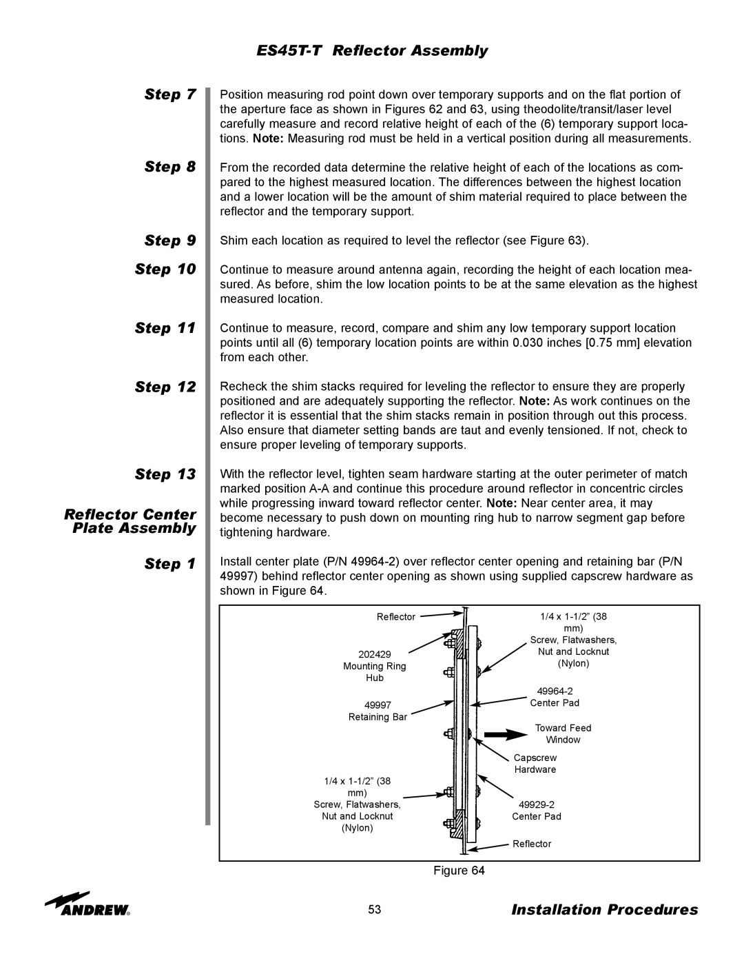
Step 1
Position measuring rod point down over temporary supports and on the flat portion of the aperture face as shown in Figures 62 and 63, using theodolite/transit/laser level carefully measure and record relative height of each of the (6) temporary support loca- tions. Note: Measuring rod must be held in a vertical position during all measurements.
From the recorded data determine the relative height of each of the locations as com- pared to the highest measured location. The differences between the highest location and a lower location will be the amount of shim material required to place between the reflector and the temporary support.
Shim each location as required to level the reflector (see Figure 63).
Continue to measure around antenna again, recording the height of each location mea- sured. As before, shim the low location points to be at the same elevation as the highest measured location.
Continue to measure, record, compare and shim any low temporary support location points until all (6) temporary location points are within 0.030 inches [0.75 mm] elevation from each other.
Recheck the shim stacks required for leveling the reflector to ensure they are properly positioned and are adequately supporting the reflector. Note: As work continues on the reflector it is essential that the shim stacks remain in position through out this process. Also ensure that diameter setting bands are taut and evenly tensioned. If not, check to ensure proper leveling of temporary supports.
With the reflector level, tighten seam hardware starting at the outer perimeter of match marked position
Install center plate (P/N
|
|
| Reflector |
|
|
| 1/4 x | ||||||||
|
|
|
|
|
|
|
|
|
|
|
| mm) | |||
|
|
|
|
|
|
|
|
| Screw, Flatwashers, | ||||||
|
|
|
|
|
|
|
|
| Nut and Locknut | ||||||
202429 |
|
|
| ||||||||||||
| Mounting Ring |
|
|
|
|
|
| (Nylon) | |||||||
|
| Hub |
|
|
|
|
|
|
|
|
|
|
| ||
|
|
|
|
|
|
|
|
|
| ||||||
|
|
|
|
|
|
| Center Pad |
| |||||||
49997 |
|
|
| ||||||||||||
|
| Retaining Bar |
|
|
|
|
|
|
|
|
|
| |||
|
|
|
|
|
|
|
|
|
| Toward Feed |
| ||||
|
|
|
|
|
|
| |||||||||
|
|
|
|
|
|
|
|
|
| Window |
| ||||
|
|
|
|
|
|
|
|
|
|
|
|
|
|
| |
|
|
|
|
|
|
|
| Capscrew | |||||||
|
|
|
|
|
|
|
| Hardware |
|
|
| ||||
1/4 x |
|
|
|
|
|
|
|
|
|
| |||||
|
|
|
|
|
|
|
|
|
|
|
| ||||
|
| mm) |
|
|
|
|
|
|
|
|
|
| |||
Screw, Flatwashers, |
|
|
|
|
|
|
|
|
| ||||||
Nut and Locknut |
|
| Center Pad |
|
|
| |||||||||
| (Nylon) |
|
|
|
|
|
|
|
|
|
| ||||
|
|
|
|
|
|
|
|
|
|
|
|
| |||
|
|
|
|
|
|
|
|
|
|
|
|
|
|
|
|
|
|
|
|
|
|
|
| Reflector | |||||||
Figure 64
53 | Installation Procedures |