Assembly
(With Hoist Kit)
Step 1
Step 2
Step 3
Step 4
Step 5
Step 6
The optional hoist kit (P/N 49080) must be assembled prior to reflector/ backstructure assembly hoisting. Hoist assembly should not be used for antenna elevation angle adjustment. The following steps provide the procedure for installing the reflector with the hoist kit.
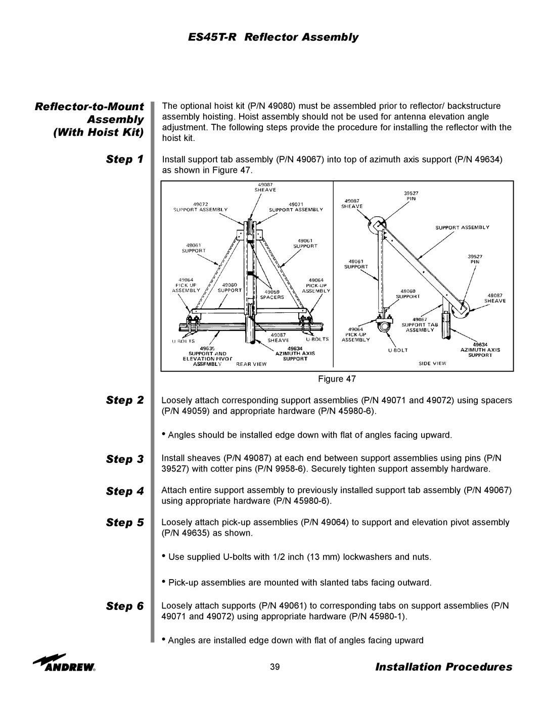
Install support tab assembly (P/N 49067) into top of azimuth axis support (P/N 49634) as shown in Figure 47.
Figure 47
Loosely attach corresponding support assemblies (P/N 49071 and 49072) using spacers (P/N 49059) and appropriate hardware (P/N
•Angles should be installed edge down with flat of angles facing upward.
Install sheaves (P/N 49087) at each end between support assemblies using pins (P/N 39527) with cotter pins (P/N
Attach entire support assembly to previously installed support tab assembly (P/N 49067) using appropriate hardware (P/N
Loosely attach
•Use supplied
•
Loosely attach supports (P/N 49061) to corresponding tabs on support assemblies (P/N 49071 and 49072) using appropriate hardware (P/N
•Angles are installed edge down with flat of angles facing upward
39 | Installation Procedures |