Andrew manual ES45T-TReflector Assembly, Step Step Step Step, Installation Procedures

Models: ES45T

1 81
Download 81 pages 35.94 Kb
Page 64
Image 64
Manual background

ES45T-T Reflector Assembly

Step 6

Step 7

Step 8

Step 9

Determine required length of azimuth strut to nearest degree increment of desired azimuth setting. Adjust coarse azimuth setting by withdrawing secondary strut section from primary strut to achieve desired strut length. Install four 1/2 inch (13 mm) set screws in holes provided and securely tighten. Note: Do not extend secondary strut section into red warning area.

Carefully pivot reflector as required and attach azimuth strut to U-bracket using previ- ously removed 3/4 x 4-1/2 inch (114 mm) bolt, lockwasher and nut. Note: Apply grease (P/N 49208) around bottom area of lower azimuth axis joint assembly (P/N 49629) before changing azimuth position of antenna.

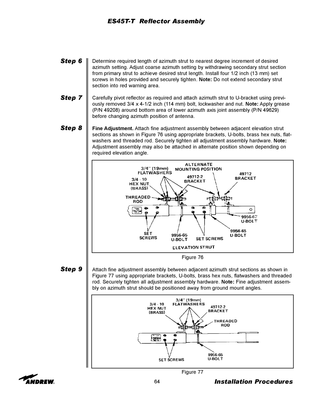
Fine Adjustment. Attach fine adjustment assembly between adjacent elevation strut sections as shown in Figure 76 using appropriate brackets, U-bolts, brass hex nuts, flat- washers and threaded rod. Securely tighten all adjustment assembly hardware. Note: Adjustment assembly may also be attached in alternate position shown depending on required elevation angle.

Figure 76

Attach fine adjustment assembly between adjacent azimuth strut sections as shown in Figure 77 using appropriate brackets, U-bolts, brass hex nuts, flatwashers and threaded rod. Securely tighten all adjustment assembly hardware. Note: Fine adjustment assem- bly on azimuth strut should be positioned away from ground mount angles.

Figure 77

64

Installation Procedures

Page 64
Image 64
Andrew manual ES45T-TReflector Assembly, Step Step Step Step, Installation Procedures