Reflector Leveling
Procedure
Step 1
Step 2
Step 3
Step 4
Step 5
Step 6
Step 7
Step 8
ES45T-R Reflector Assembly
Position (6) temporary supports near panel seams exactly as shown in Figure 29. Note: Temporary supports should be large enough to adequately support the reflector and strong enough to easily support reflector weight without compressing.
Position theodolite, transit or laser level about 10 feet [3m] from outside perimeter of reflector (see Figure 30).
Level theodolite/transit/laser level. If using theodolite, position view scope at 0.0 degrees elevation, lock down elevation adjustment.
Site through theodolite/transit/laser level to determine where on measuring rod to place steel rule onto rod to allow visibility of steel rule through theodolite/transit at all (6) six measurement locations around reflector. Securely fasten both ends of steel rule to mea- suring rod with adhesive tape (see Figure 30).
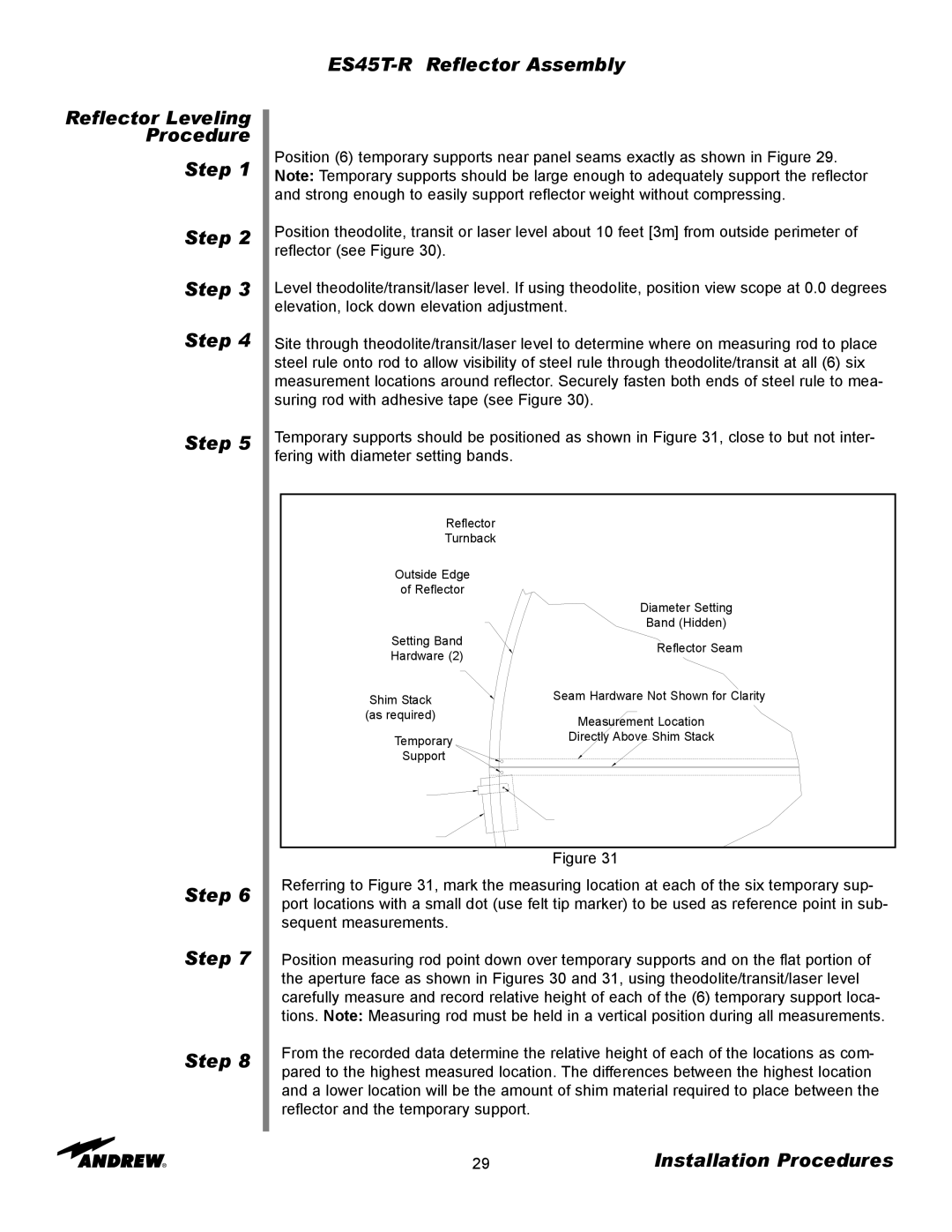
Temporary supports should be positioned as shown in Figure 31, close to but not inter- fering with diameter setting bands.
Reflector
Turnback
Outside Edge
of Reflector
| Diameter Setting | |
| Band (Hidden) | |
Setting Band | Reflector Seam | |
Hardware (2) | ||
| ||
Shim Stack | Seam Hardware Not Shown for Clarity | |
(as required) | Measurement Location | |
| ||
Temporary | Directly Above Shim Stack | |
Support |
|
Figure 31
Referring to Figure 31, mark the measuring location at each of the six temporary sup- port locations with a small dot (use felt tip marker) to be used as reference point in sub- sequent measurements.
Position measuring rod point down over temporary supports and on the flat portion of the aperture face as shown in Figures 30 and 31, using theodolite/transit/laser level carefully measure and record relative height of each of the (6) temporary support loca- tions. Note: Measuring rod must be held in a vertical position during all measurements.
From the recorded data determine the relative height of each of the locations as com- pared to the highest measured location. The differences between the highest location and a lower location will be the amount of shim material required to place between the reflector and the temporary support.
29 | Installation Procedures |