ES45T-R Reflector Assembly
Step 10
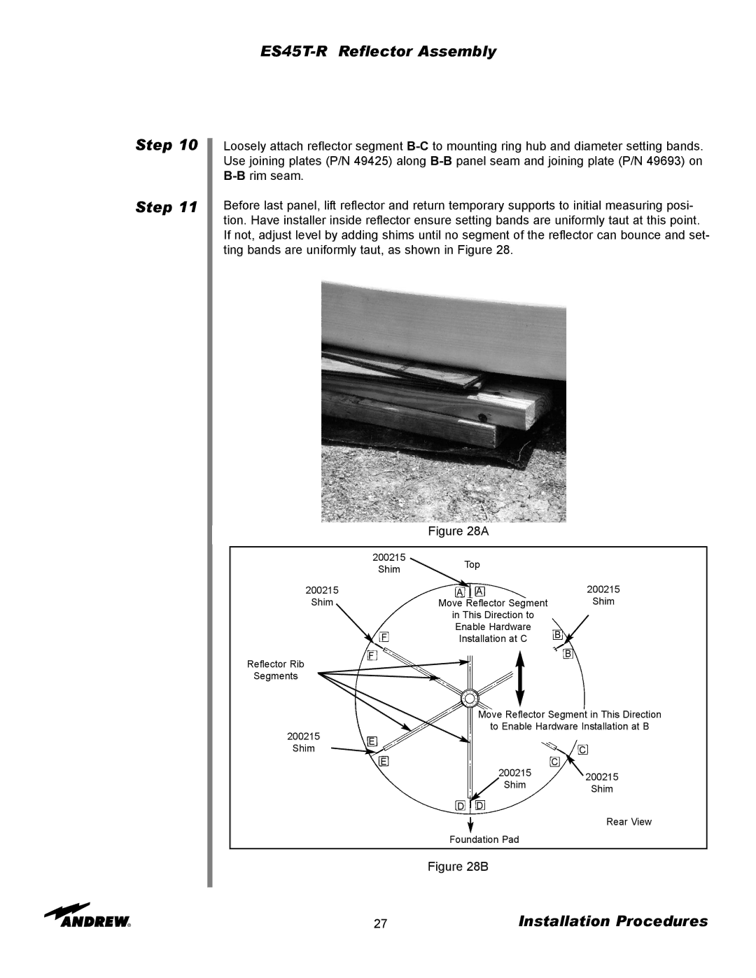
Step 11
Loosely attach reflector segment
Before last panel, lift reflector and return temporary supports to initial measuring posi- tion. Have installer inside reflector ensure setting bands are uniformly taut at this point. If not, adjust level by adding shims until no segment of the reflector can bounce and set- ting bands are uniformly taut, as shown in Figure 28.
Figure 28A
200215
Shim
200215
Shim
![]() Top
Top
AA
Move Reflector Segment
200215
Shim
Reflector Rib
Segments
F
F
in This Direction to Enable Hardware Installation at C
B![]()
B
Move Reflector Segment in This Direction
to Enable Hardware Installation at B
200215 E
Shim
E
| C | |
| C | |
200215 |
|
|
| 200215 | |
Shim |
| |
| Shim | |
|
| |
|
|
|
D D
![]() Rear View Foundation Pad
Rear View Foundation Pad
Figure 28B
27 | Installation Procedures |