Chapter 4 Measurements
Device Under Test
TMA-D
Procedure
Step 1. Connect the External Power Supply
Step 3. Select INSERTION GAIN
ENTER.
Step 4. Press the FREQ/DIST key to set the frequency limits. For a
Step 5. Perform a
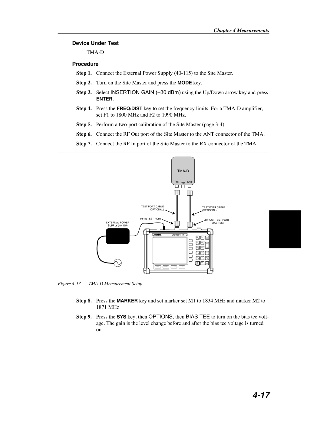
Step 6. Connect the RF Out port of the Site Master to the ANT connector of the TMA. Step 7. Connect the RF In port of the Site Master to the RX connector of the TMA
TMA-D
TEST PORT CABLE (OPTIONAL)
RF IN TEST PORT
EXTERNAL POWER
SUPPLY
RX TX ANT
TEST PORT CABLE (OPTIONAL)
RF OUT TEST PORT
(BIAS TEE)
Site Master S251C
1 | 2 |
START AUTO
CAL SCALE
3 4
SAVE RECALL
SETUP SETUP
5 6
LIMIT MARKER
7 8
ESCAPE
CLEAR
ENTER
SAVE RECALL RUN
DISPLAY DISPLAY HOLD
9 0 +/-
ON PRINT
OFF.
MODE | FREQ/DIST | AMPLITUDE | SWEEP |
Figure 4-13. TMA-D Measurement Setup
SYS
Step 8. Press the MARKER key and set marker set M1 to 1834 MHz and marker M2 to 1871 MHz
Step 9. Press the SYS key, then OPTIONS, then BIAS TEE to turn on the bias tee volt- age. The gain is the level change before and after the bias tee voltage is turned on.