Asante Technologies IC3624PWR user manual Interpreting LEDs, Network Wiring Connections

Models: IC3624PWR

1 87
Download 87 pages 5.78 Kb
Page 20
Image 20

20

4.1.3 Network Wiring Connections

The punch-down block is an integral part of many of the newer equipment racks. It is actually part of the patch panel. Instructions for making connections in the wiring closet with this type of equipment follows.

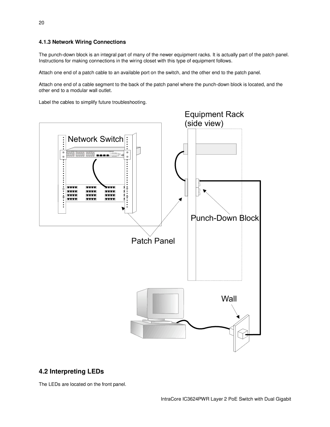
Attach one end of a patch cable to an available port on the switch, and the other end to the patch panel.

Attach one end of a cable segment to the back of the patch panel where the punch-down block is located, and the other end to a modular wall outlet.

Label the cables to simplify future troubleshooting.

Network Switch

Patch Panel

Equipment Rack (side view)

Punch-Down Block

Wall

4.2 Interpreting LEDs

The LEDs are located on the front panel.

IntraCore IC3624PWR Layer 2 PoE Switch with Dual Gigabit

Page 20
Image 20
Asante Technologies IC3624PWR user manual Interpreting LEDs, Network Wiring Connections