Asante Technologies IC3624PWR user manual Appendix C Cables and Pin Assignments

Models: IC3624PWR

1 87
Download 87 pages 5.78 Kb
Page 81
Image 81

81

Appendix C: Cables and Pin Assignments

This Appendix describes the information on 10BaseT/100BaseTX, 1000BaseT, and testing for existing Category 5 cables.

C.1 Twisted-Pair Cable and Pin Assignments

For 10BaseT/100BaseTX connections, a twisted-pair cable must have two pairs of wires. Each wire pair is identified by two different colors. For example, one green wire and another green with white stripes. You must attach an RJ-45 connector to both ends of the cable.

Warning: DO NOT plug a phone jack connector into any RJ-45 port. This will damage the switch. Use only twisted- pair cables with RJ-45 connectors that conform to FCC standards.

Caution: Attach each wire pair to the RJ-45 connectors in a specific orientation. (See “ 4.1.1 Cable Guidelines” for more information.)

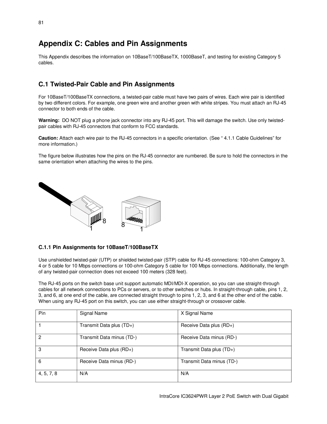
The figure below illustrates how the pins on the RJ-45 connector are numbered. Be sure to hold the connectors in the same orientation when attaching the wires to the pins.


8

8

1


1

C.1.1 Pin Assignments for 10BaseT/100BaseTX

Use unshielded twisted-pair (UTP) or shielded twisted-pair (STP) cable for RJ-45 connections: 100-ohm Category 3,

4 or 5 cable for 10 Mbps connections or 100-ohm Category 5 cable for 100 Mbps connections. Additionally, the length of any twisted-pair connection does not exceed 100 meters (328 feet).

The RJ-45 ports on the switch base unit support automatic MDI/MDI-X operation, so you can use straight-through cables for all network connections to PCs or servers, or to other switches or hubs. In straight-through cable, pins 1, 2, 3, and 6, at one end of the cable, are connected straight through to pins 1, 2, 3, and 6 at the other end of the cable. When using any RJ-45 port on this switch, you can use either straight-through or crossover cable.

Pin

Signal Name

X Signal Name


1

Transmit Data plus (TD+)

Receive Data plus (RD+)


2

Transmit Data minus (TD-)

Receive Data minus (RD-)


3

Receive Data plus (RD+)

Transmit Data plus (TD+)


6

Receive Data minus (RD-)

Transmit Data minus (TD-)


4, 5, 7, 8

N/A

N/A


IntraCore IC3624PWR Layer 2 PoE Switch with Dual Gigabit

Page 81
Image 81
Asante Technologies IC3624PWR user manual Appendix C Cables and Pin Assignments, Twisted-Pair Cable and Pin Assignments