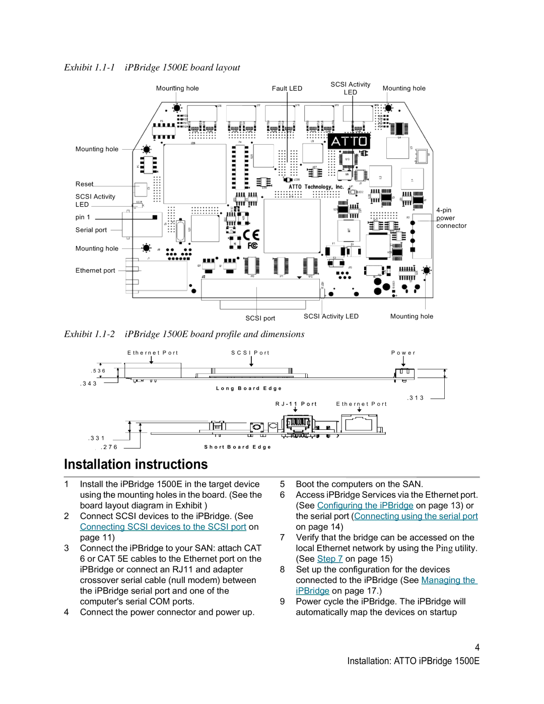
Exhibit 1.1-1 iPBridge 1500E board layout
Mounting hole
Reset
SCSI Activity
LED
pin 1
Serial port
Mounting hole
Ethernet port
SCSI Activity
Mounting holeFault LEDMounting hole
LED
SCSI port | SCSI Activity LED | Mounting hole |
Exhibit 1.1-2 iPBridge 1500E board profile and dimensions
E t h e r n e t P o r t | S C S I P o r t | P o w e r |
. 5 3 6
. 3 4 3
L o n g B o a r d E d g e
. 3 1 3
R J - 1 1 P o r t | E t h e r n e t P o r t |
. 3 3 1
. 2 7 6 | S h o r t B o a r d E d g e |
|
|
Installation instructions
1Install the iPBridge 1500E in the target device using the mounting holes in the board. (See the board layout diagram in Exhibit )
2Connect SCSI devices to the iPBridge. (See Connecting SCSI devices to the SCSI port on page 11)
3Connect the iPBridge to your SAN: attach CAT 6 or CAT 5E cables to the Ethernet port on the iPBridge or connect an RJ11 and adapter crossover serial cable (null modem) between the iPBridge serial port and one of the computer's serial COM ports.
4Connect the power connector and power up.
5Boot the computers on the SAN.
6Access iPBridge Services via the Ethernet port. (See Configuring the iPBridge on page 13) or the serial port (Connecting using the serial port on page 14)
7Verify that the bridge can be accessed on the local Ethernet network by using the Ping utility. (See Step 7 on page 15)
8Set up the configuration for the devices connected to the iPBridge (See Managing the iPBridge on page 17.)
9Power cycle the iPBridge. The iPBridge will automatically map the devices on startup
4 Installation: ATTO iPBridge 1500E