1.2 ATTO iPBridge 1500D
The ATTO iPBridge 1500D is a
The iPBridge 1500E includes a single Ethernet port which may be used for either data transfer or configuration, a serial management port and a SCSI port.
Dimensions
Width: 7.5 inches wide
Depth: 5.0 inches long
Height: 1.76 inches
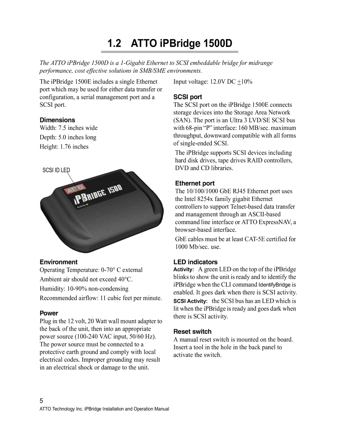
SCSI ID LED
Input voltage: 12.0V DC +10%
SCSI port
The SCSI port on the iPBridge 1500E connects storage devices into the Storage Area Network (SAN). The port is an Ultra 3 LVD/SE SCSI bus with
The iPBridge supports SCSI devices including hard disk drives, tape drives RAID controllers, DVD and CD libraries.
Ethernet port
The 10/100/1000 GbE RJ45 Ethernet port uses the Intel 8254x family gigabit Ethernet controllers to support
GbE cables must be at least
Environment
Operating Temperature:
Power
Plug in the 12 volt, 20 Watt wall mount adapter to the back of the unit, then into an appropriate power source
LED indicators
Activity: A green LED on the top of the iPBridge blinks to show the unit is ready and to identify the iPBridge when the CLI command IdentifyBridge is enabled. It goes dark when there is SCSI activity. SCSI Activity: the SCSI bus has an LED which is lit when the iPBridge is ready and goes dark when there is SCSI activity.
Reset switch
A manual reset switch is mounted on the board. Insert a tool in the hole in the back panel to activate the switch.
5
ATTO Technology Inc. iPBridge Installation and Operation Manual