Chapter 4 | Installation |
|
|
4If you wish to implement stack redundancy, use the Redundant Cable to connect the port marked “to lower unit” on the bottom switch to the port marked “to upper unit” on top switch of the stack.
5Power up the added modules.
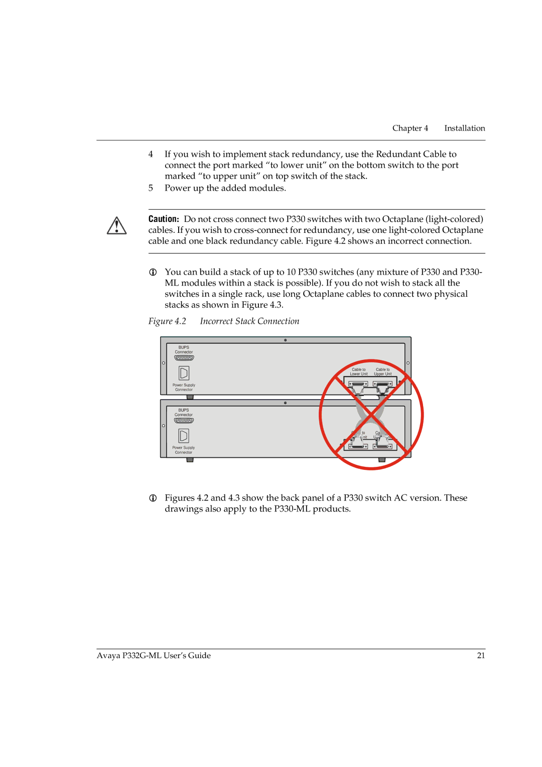
Caution: Do not cross connect two P330 switches with two Octaplane
You can build a stack of up to 10 P330 switches (any mixture of P330 and P330- ML modules within a stack is possible). If you do not wish to stack all the switches in a single rack, use long Octaplane cables to connect two physical stacks as shown in Figure 4.3.
Figure 4.2 Incorrect Stack Connection
BUPS
Connector
Cable to | Cable to |
Lower Unit | Upper Unit |
Power Supply
Connector
BUPS
Connector
to
Lower![]()
![]() Unit Uppe
Unit Uppe![]() r
r ![]() Unit
Unit
Power Supply
Connector
Figures 4.2 and 4.3 show the back panel of a P330 switch AC version. These drawings also apply to the P330-ML products.
Avaya | 21 |