PLENA matrixInstallation en 15
5.3Wall Control Panel
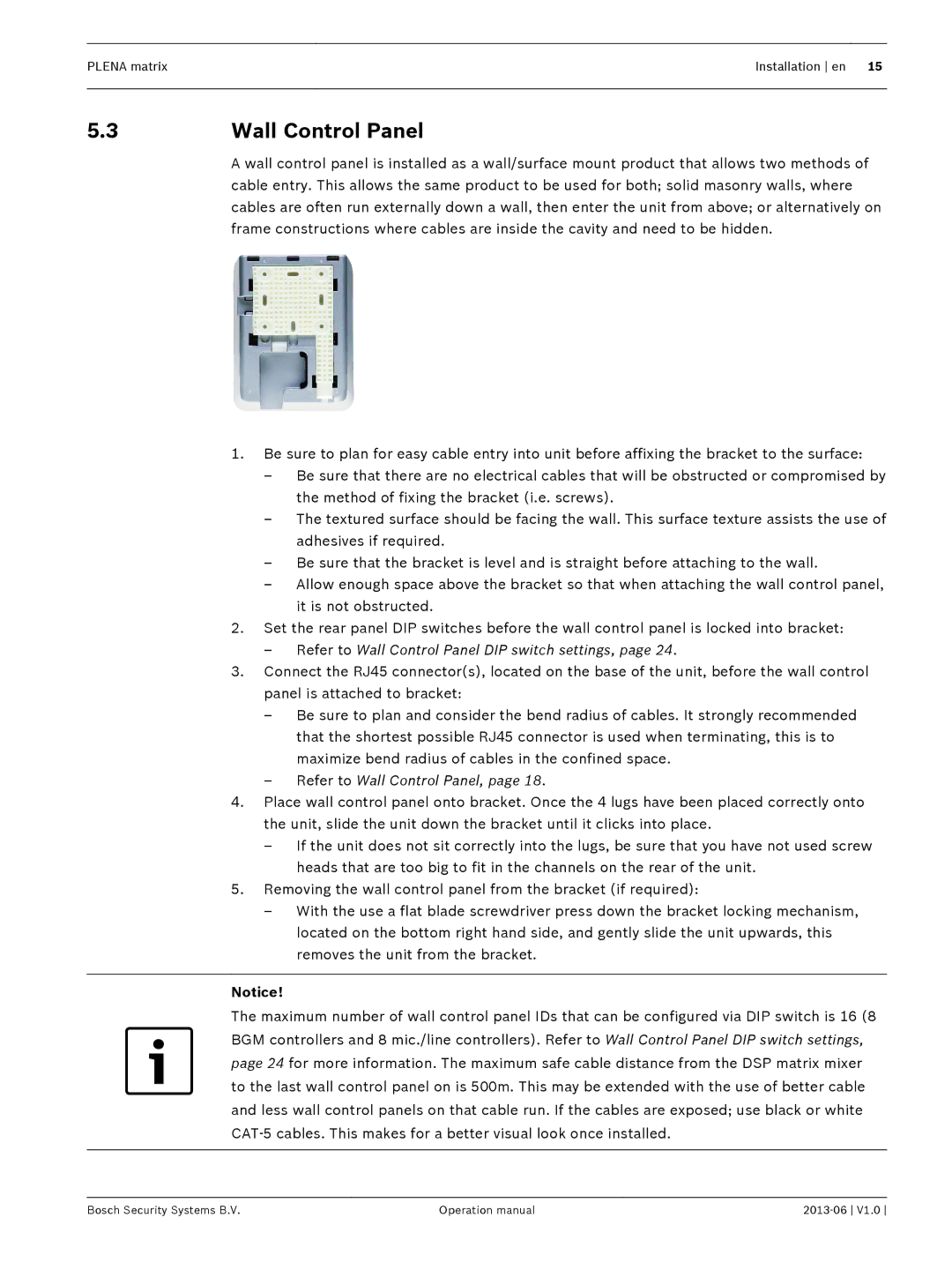
A wall control panel is installed as a wall/surface mount product that allows two methods of cable entry. This allows the same product to be used for both; solid masonry walls, where cables are often run externally down a wall, then enter the unit from above; or alternatively on frame constructions where cables are inside the cavity and need to be hidden.
1.Be sure to plan for easy cable entry into unit before affixing the bracket to the surface:
–Be sure that there are no electrical cables that will be obstructed or compromised by the method of fixing the bracket (i.e. screws).
–The textured surface should be facing the wall. This surface texture assists the use of adhesives if required.
–Be sure that the bracket is level and is straight before attaching to the wall.
–Allow enough space above the bracket so that when attaching the wall control panel, it is not obstructed.
2.Set the rear panel DIP switches before the wall control panel is locked into bracket:
–Refer to Wall Control Panel DIP switch settings, page 24.
3.Connect the RJ45 connector(s), located on the base of the unit, before the wall control panel is attached to bracket:
–Be sure to plan and consider the bend radius of cables. It strongly recommended that the shortest possible RJ45 connector is used when terminating, this is to maximize bend radius of cables in the confined space.
–Refer to Wall Control Panel, page 18.
4.Place wall control panel onto bracket. Once the 4 lugs have been placed correctly onto the unit, slide the unit down the bracket until it clicks into place.
–If the unit does not sit correctly into the lugs, be sure that you have not used screw heads that are too big to fit in the channels on the rear of the unit.
5.Removing the wall control panel from the bracket (if required):
–With the use a flat blade screwdriver press down the bracket locking mechanism, located on the bottom right hand side, and gently slide the unit upwards, this removes the unit from the bracket.
Notice!
The maximum number of wall control panel IDs that can be configured via DIP switch is 16 (8 BGM controllers and 8 mic./line controllers). Refer to Wall Control Panel DIP switch settings, page 24 for more information. The maximum safe cable distance from the DSP matrix mixer to the last wall control panel on is 500m. This may be extended with the use of better cable and less wall control panels on that cable run. If the cables are exposed; use black or white CAT‑5 cables. This makes for a better visual look once installed.
Bosch Security Systems B.V. | Operation manual |