PLENA matrixConnections en 19
6.3 | Multi channel DSP Amplifier |
|
| |
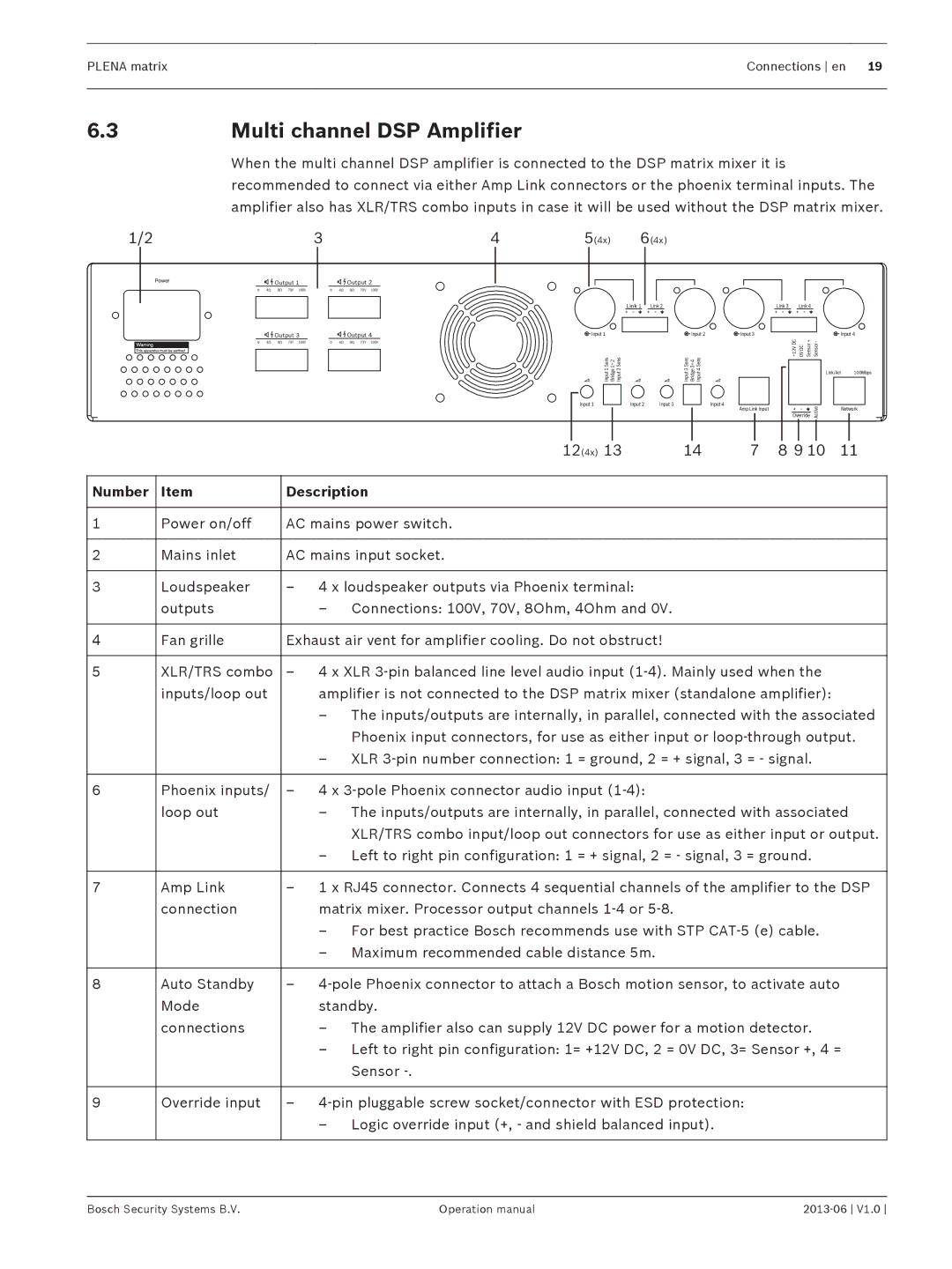
| When the multi channel DSP amplifier is connected to the DSP matrix mixer it is | |||
| recommended to connect via either Amp Link connectors or the phoenix terminal inputs. The | |||
| amplifier also has XLR/TRS combo inputs in case it will be used without the DSP matrix mixer. | |||
1/2 | 3 | 4 | 5(4x) | 6(4x) |
|
|
| POWER |
| Output 1 | ||||||||
|
|
|
|
|
|
|
|
|
|
| |||
|
|
| 0 | 4Ω | 8Ω | 70V | 100V | ||||||
|
|
| |||||||||||
|
|
|
|
|
|
|
|
|
|
|
| ||
|
|
|
|
|
|
|
|
|
|
|
|
|
|
|
|
|
|
|
|
|
|
|
|
|
|
|
|
|
|
|
|
|
|
|
|
|
|
| Output 3 | ||
|
|
|
|
|
|
|
|
|
|
| |||
|
|
|
|
| 0 | 4Ω | 8Ω | 70V | 100V | ||||
|
|
|
|
|
|
|
|
|
|
|
|
|
|
![]()
![]() Output 2
Output 2
0 4Ω 8Ω 70V 100V
![]()
![]() Output 4
Output 4
0 4Ω 8Ω 70V 100V
![]() Input 1
Input 1
Input 2 Sens
Bridge 1+2
Input 1 Sens
Input 1
Link 1 Link 2
Input 2 | Input 3 |
| Link 3 | Link 4 |
|
|
Input 2 | Input 3 |
| Input 4 | |
Input3 Sens Bridge3+4 Input4 Sens | +12V DC | 0V DC Sensor + | Sensor - |
|
|
| Link/Act | 100Mbps | |
| Input 4 |
| Active |
|
| Override |
| ||
| Amp Link Input |
|
| Network |
|
| 12(4x) | 13 | 14 | 7 | 8 9 10 | 11 |
|
|
|
|
|
|
|
|
Number | Item | Description |
|
|
|
|
|
|
|
|
|
|
|
|
|
1 | Power on/off | AC mains power switch. |
|
|
|
|
|
|
|
|
|
|
|
|
|
2 | Mains inlet | AC mains input socket. |
|
|
|
|
|
|
|
|
|
|
|
| |
3 | Loudspeaker | – 4 x loudspeaker outputs via Phoenix terminal: |
|
|
|
| |
| outputs | – Connections: 100V, 70V, 8Ohm, 4Ohm and 0V. |
|
|
|
| |
|
|
|
|
|
|
| |
4 | Fan grille | Exhaust air vent for amplifier cooling. Do not obstruct! |
|
|
|
| |
|
|
|
| ||||
5 | XLR/TRS combo | – 4 x XLR |
| ||||
| inputs/loop out | amplifier is not connected to the DSP matrix mixer (standalone amplifier): |
| ||||
|
| – The inputs/outputs are internally, in parallel, connected with the associated | |||||
|
| Phoenix input connectors, for use as either input or loop‑through output. | |||||
|
| – XLR |
| ||||
|
|
|
|
|
|
| |
6 | Phoenix inputs/ | – 4 x |
|
|
|
| |
| loop out | – The inputs/outputs are internally, in parallel, connected with associated | |||||
|
| XLR/TRS combo input/loop out connectors for use as either input or output. | |||||
|
| – Left to right pin configuration: 1 = + signal, 2 = - signal, 3 = ground. |
| ||||
|
|
| |||||
7 | Amp Link | – 1 x RJ45 connector. Connects 4 sequential channels of the amplifier to the DSP | |||||
| connection | matrix mixer. Processor output channels |
|
|
|
| |
|
| – For best practice Bosch recommends use with STP CAT‑5 (e) cable. |
| ||||
|
| – Maximum recommended cable distance 5m. |
|
|
|
| |
|
|
| |||||
8 | Auto Standby | – 4‑pole Phoenix connector to attach a Bosch motion sensor, to activate auto | |||||
| Mode | standby. |
|
|
|
|
|
| connections | – The amplifier also can supply 12V DC power for a motion detector. |
| ||||
|
| – Left to right pin configuration: 1= +12V DC, 2 = 0V DC, 3= Sensor +, 4 = | |||||
|
| Sensor |
|
|
|
|
|
|
|
|
|
|
| ||
9 | Override input | – |
|
|
| ||
|
| – Logic override input (+, - and shield balanced input). |
|
|
| ||
|
|
|
|
|
|
|
|
Bosch Security Systems B.V. | Operation manual |