PLENA matrixConnections en 21
6.4DSP Matrix Mixer
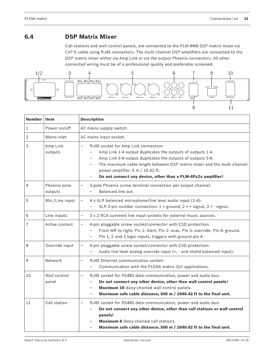
Call stations and wall control panels, are connected to the PLM‑8M8 DSP matrix mixer via CAT‑5 cable using RJ45 connectors. The multi channel DSP amplifiers are connected to the DSP matrix mixer either via Amp Link or via the output Phoenix connectors. All other connected wiring must be of a professional quality and preferable screened.
1/2 | 3 |
| 4 |
|
|
| 5 |
|
| 6 |
|
POWER | Amp Link Out | Out 1 | Out 2 | Out 3 | Out 4 |
|
|
|
|
|
|
|
|
|
|
|
|
| |||||
|
|
|
|
|
|
|
|
| L |
|
|
|
|
|
|
|
|
|
|
| R |
|
|
| Amp Link Out |
|
|
| Mic/Line 1 | Mic/Line 2 | Mic/Line 3 | Mic/Line 4 | Line 5 | Line 6 | Line 7 |
|
| Out 5 | Out 6 | Out 7 | Out 8 |
|
|
|
|
|
|
7
N.C. | Alert | Evac | Active | |
|
|
|
|
|
|
|
|
| 0V |
Override
910
Control Panels
Link/Act100Mbps
Network | Call Stations |
|
| 8 | 11 |
|
|
|
|
Number | Item | Description |
|
|
|
|
|
1 | Power on/off | AC mains supply switch. |
|
|
|
|
|
2 | Mains inlet | AC mains input socket. |
|
|
|
|
|
3 | Amp Link | – RJ45 socket for Amp Link connection: |
|
| outputs | – Amp Link 1‑4 output duplicates the outputs of outputs 1‑4. |
|
|
| – Amp Link 5‑8 output duplicates the outputs of outputs 5‑8. |
|
|
| – The maximum cable lenght between DSP matrix mixer and the multi channel | |
|
| power amplifier: 5 m / 16.42 ft. |
|
|
| – Do not connect any device, other than a PLM‑4Px2x amplifier! |
|
|
|
|
|
4 | Phoenix zone | – 3‑pole Phoenix screw terminal connection per output channel: |
|
| outputs | – Balanced line out. |
|
|
|
|
|
5 | Mic./Line input | – 4 x XLR balanced microphone/line level audio input |
|
|
| – XLR 3‑pin number connection: 1 = ground, 2 = + signal, 3 = - signal. | |
|
|
|
|
6 | Line inputs | – 3 x 2 RCA summed line input sockets for external music sources. |
|
|
|
|
|
7 | Active contact | – 4‑pin pluggable screw socket/connector with ESD protection: |
|
|
| – From left to right; Pin 1: Alert, Pin 2: evac, Pin 3: override, Pin 4: ground. | |
|
| – Pin 1, 2 and 3 logic inputs, triggers with ground pin 4. |
|
|
|
|
|
8 | Override input | – |
|
|
| – Audio line level analog override input (+, - and shield balanced input). | |
|
|
|
|
9 | Network | – RJ45 Ethernet communication socket: |
|
|
| – Communication with the PLENA matrix GUI applications. |
|
|
|
|
|
10 | Wall control | – RJ45 socket for RS485 data communication, power and audio bus: |
|
| panel | – Do not connect any other device, other than wall control panels! |
|
|
| – Maximum 16 daisy‑chained wall control panels. |
|
|
| – Maximum safe cable distance; 500 m / 1640.42 ft to the final unit. | |
|
|
|
|
11 | Call station | – RJ45 socket for RS485 data communication, power and audio bus: |
|
|
| – Do not connect any other device, other than call stations or wall control | |
|
| panels! |
|
|
| – Maximum 8 daisy‑chained call stations. |
|
|
| – Maximum safe cable distance; 500 m / 1640.42 ft to the final unit. | |
|
|
|
|
|
|
|
|
Bosch Security Systems B.V. | Operation manual |
