24 en ConfigurationPLENA matrix
7.2 | Wall Control Panel DIP switch settings |
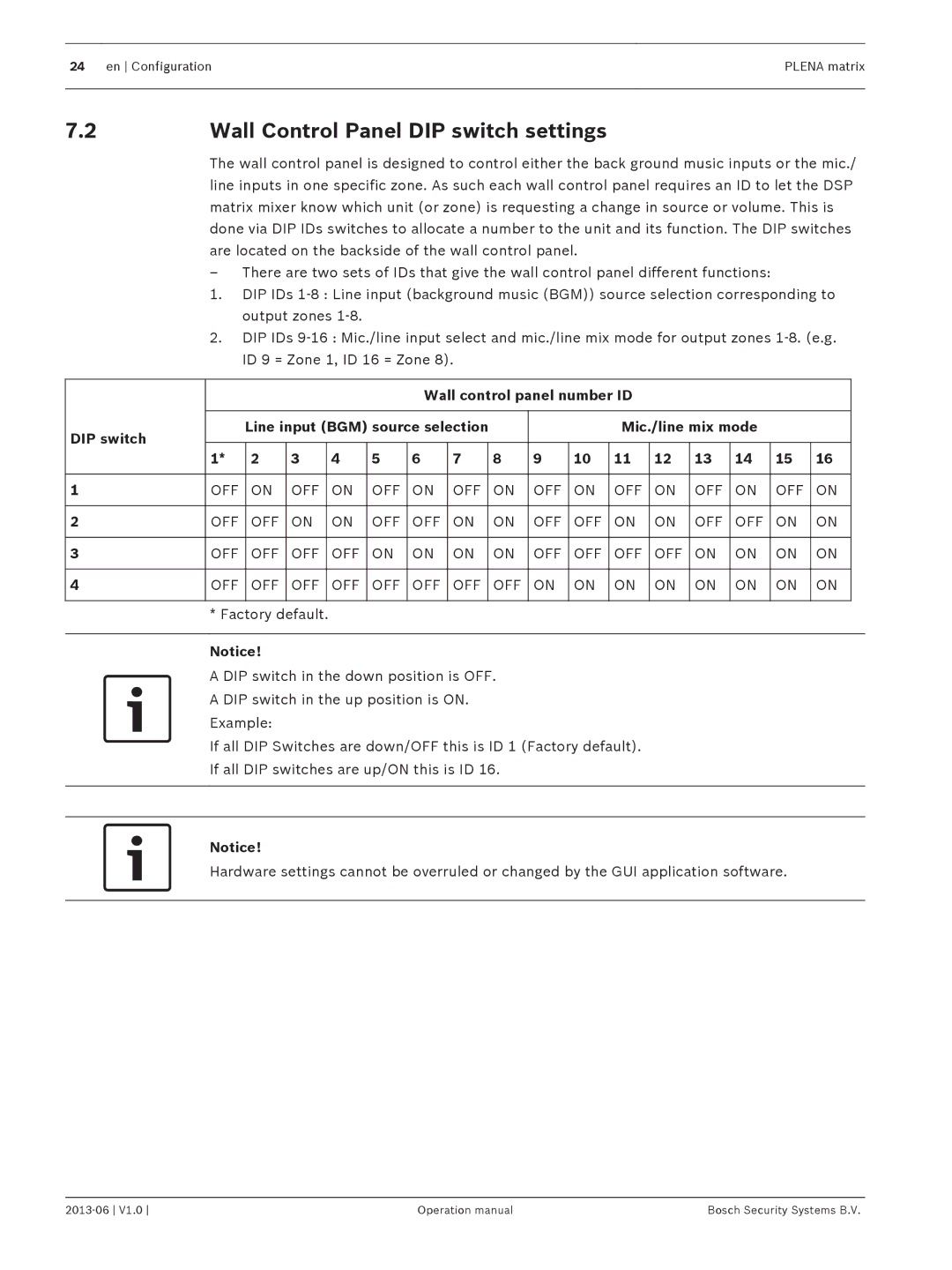
The wall control panel is designed to control either the back ground music inputs or the mic./ line inputs in one specific zone. As such each wall control panel requires an ID to let the DSP matrix mixer know which unit (or zone) is requesting a change in source or volume. This is done via DIP IDs switches to allocate a number to the unit and its function. The DIP switches are located on the backside of the wall control panel.
–There are two sets of IDs that give the wall control panel different functions:
1.DIP IDs 1‑8 : Line input (background music (BGM)) source selection corresponding to output zones 1‑8.
2.DIP IDs 9‑16 : Mic./line input select and mic./line mix mode for output zones 1‑8. (e.g. ID 9 = Zone 1, ID 16 = Zone 8).
|
|
|
|
|
| Wall control panel number ID |
|
|
|
|
| ||||||
|
|
|
|
|
|
|
|
|
|
|
|
|
|
|
|
|
|
DIP switch |
| Line input (BGM) source selection |
|
|
| Mic./line mix mode |
|
| |||||||||
|
|
|
|
|
|
|
|
|
|
|
|
|
|
|
|
| |
| 1* | 2 | 3 | 4 | 5 | 6 | 7 |
| 8 | 9 | 10 | 11 | 12 | 13 | 14 | 15 | 16 |
|
|
|
|
|
|
|
|
|
|
|
|
|
|
|
|
|
|
1 | OFF | ON | OFF | ON | OFF | ON | OFF |
| ON | OFF | ON | OFF | ON | OFF | ON | OFF | ON |
|
|
|
|
|
|
|
|
|
|
|
|
|
|
|
|
|
|
2 | OFF | OFF | ON | ON | OFF | OFF | ON |
| ON | OFF | OFF | ON | ON | OFF | OFF | ON | ON |
|
|
|
|
|
|
|
|
|
|
|
|
|
|
|
|
|
|
3 | OFF | OFF | OFF | OFF | ON | ON | ON |
| ON | OFF | OFF | OFF | OFF | ON | ON | ON | ON |
|
|
|
|
|
|
|
|
|
|
|
|
|
|
|
|
|
|
4 | OFF | OFF | OFF | OFF | OFF | OFF | OFF |
| OFF | ON | ON | ON | ON | ON | ON | ON | ON |
|
|
|
|
|
|
|
|
|
|
|
|
|
|
|
|
|
|
* Factory default.
Notice!
A DIP switch in the down position is OFF.
A DIP switch in the up position is ON.
Example:
If all DIP Switches are down/OFF this is ID 1 (Factory default).
If all DIP switches are up/ON this is ID 16.
Notice!
Hardware settings cannot be overruled or changed by the GUI application software.
Operation manual | Bosch Security Systems B.V. |