38 en Operation | PLENA matrix |
|
|
The following operations can be done when using the amplifier hardware in either mode or operation:
–Activate the active override audio input function, page 38.
–Activate the amplifier auto standby, page 38.
8.4.1 | Activate the active override audio input function | |||
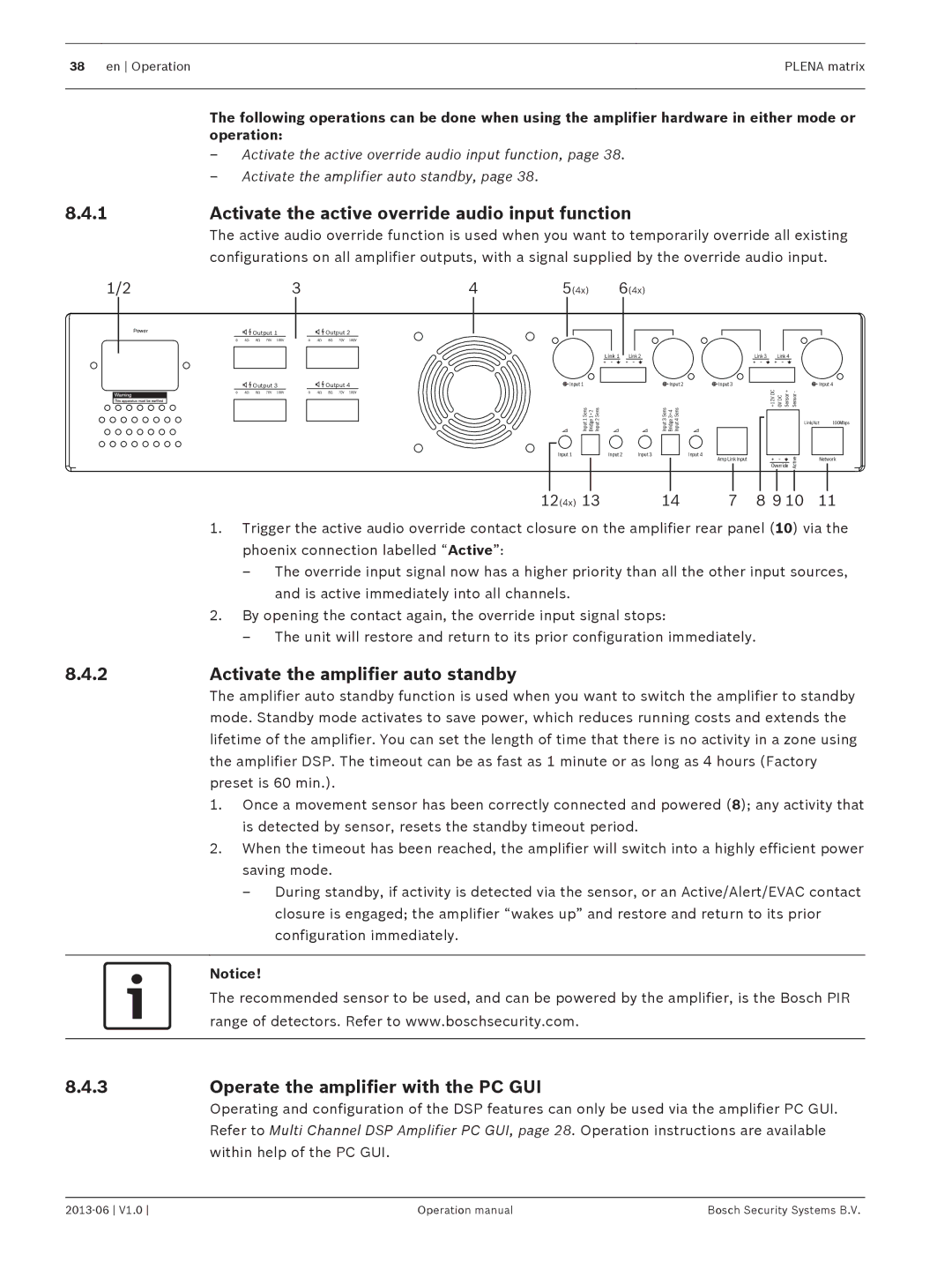
| The active audio override function is used when you want to temporarily override all existing | |||
| configurations on all amplifier outputs, with a signal supplied by the override audio input. | |||
1/2 | 3 | 4 | 5(4x) | 6(4x) |
| POWER |
| Output 1 | |||||||
|
|
|
|
|
|
|
| |||
|
| 0 | 4Ω | 8Ω | 70V | 100V | ||||
|
| |||||||||
|
|
|
|
|
|
|
|
| ||
|
|
|
|
|
|
|
|
|
|
|
|
|
|
|
|
|
|
|
|
|
|
|
|
|
|
|
|
|
| Output 3 | ||
|
|
|
|
|
|
|
| |||
|
| 0 | 4Ω | 8Ω | 70V | 100V | ||||
|
|
|
|
|
|
|
|
|
|
|
|
|
|
|
|
|
|
|
|
|
|
Output 2
0 4Ω 8Ω 70V 100V
Output 4
0 4Ω 8Ω 70V 100V
![]() Input 1
Input 1
Input 2 Sens
Bridge 1+2
Input 1 Sens
Input 1
Link 1 Link 2
Input 2 | Input 3 |
| Link 3 | Link 4 |
|
|
Input 2 | Input 3 |
| Input 4 | |
Input3 Sens Bridge3+4 Input4 Sens | +12V DC | 0V DC Sensor + | Sensor - |
|
|
| Link/Act | 100Mbps | |
| Input 4 |
| Active |
|
| Override |
| ||
| Amp Link Input |
|
| Network |
12(4x) | 13 | 14 | 7 | 8 9 10 | 11 |
1.Trigger the active audio override contact closure on the amplifier rear panel (10) via the phoenix connection labelled “Active”:
–The override input signal now has a higher priority than all the other input sources, and is active immediately into all channels.
2.By opening the contact again, the override input signal stops:
–The unit will restore and return to its prior configuration immediately.
8.4.2 | Activate the amplifier auto standby |
| The amplifier auto standby function is used when you want to switch the amplifier to standby |
| mode. Standby mode activates to save power, which reduces running costs and extends the |
| lifetime of the amplifier. You can set the length of time that there is no activity in a zone using |
| the amplifier DSP. The timeout can be as fast as 1 minute or as long as 4 hours (Factory |
| preset is 60 min.). |
| 1. Once a movement sensor has been correctly connected and powered (8); any activity that |
| is detected by sensor, resets the standby timeout period. |
| 2. When the timeout has been reached, the amplifier will switch into a highly efficient power |
| saving mode. |
| – During standby, if activity is detected via the sensor, or an Active/Alert/EVAC contact |
| closure is engaged; the amplifier “wakes up” and restore and return to its prior |
| configuration immediately. |
|
|
| Notice! |
| The recommended sensor to be used, and can be powered by the amplifier, is the Bosch PIR |
| range of detectors. Refer to www.boschsecurity.com. |
|
|
8.4.3Operate the amplifier with the PC GUI
Operating and configuration of the DSP features can only be used via the amplifier PC GUI. Refer to Multi Channel DSP Amplifier PC GUI, page 28. Operation instructions are available within help of the PC GUI.
Operation manual | Bosch Security Systems B.V. |
