COPPER BRUTE II (500 - 2000) | Page 39 |
|
|
|
|
delay setting of 5 minutes. See Section 6.4.6 for more information.
NOTE: In modes other than mode 6, the pump will run continuously if the “HtD” and “ComD” terminals are jumpered and not connected to a zone valve or pump end switch, or other “contact closure” device to indicate when the heat demand in the system is satisfied. The pump will never run, and the boiler will never fire, if the jumper is removed and the terminals left empty.
OUTDOOR RESET (modes 4 and 5): Outdoor reset adjusts the target temperature based on the outdoor air temperature and reset ratio. The reset ratio is determined from the Boiler Start, Boiler Design, Outdoor Start and Outdoor Design settings.
HEAT DEMAND – For heat demand to exist, there must be continuity between the Com D (common demand) and Ht D (heat demand) terminals. The Copper Brute II ships with a jumper between these terminals.
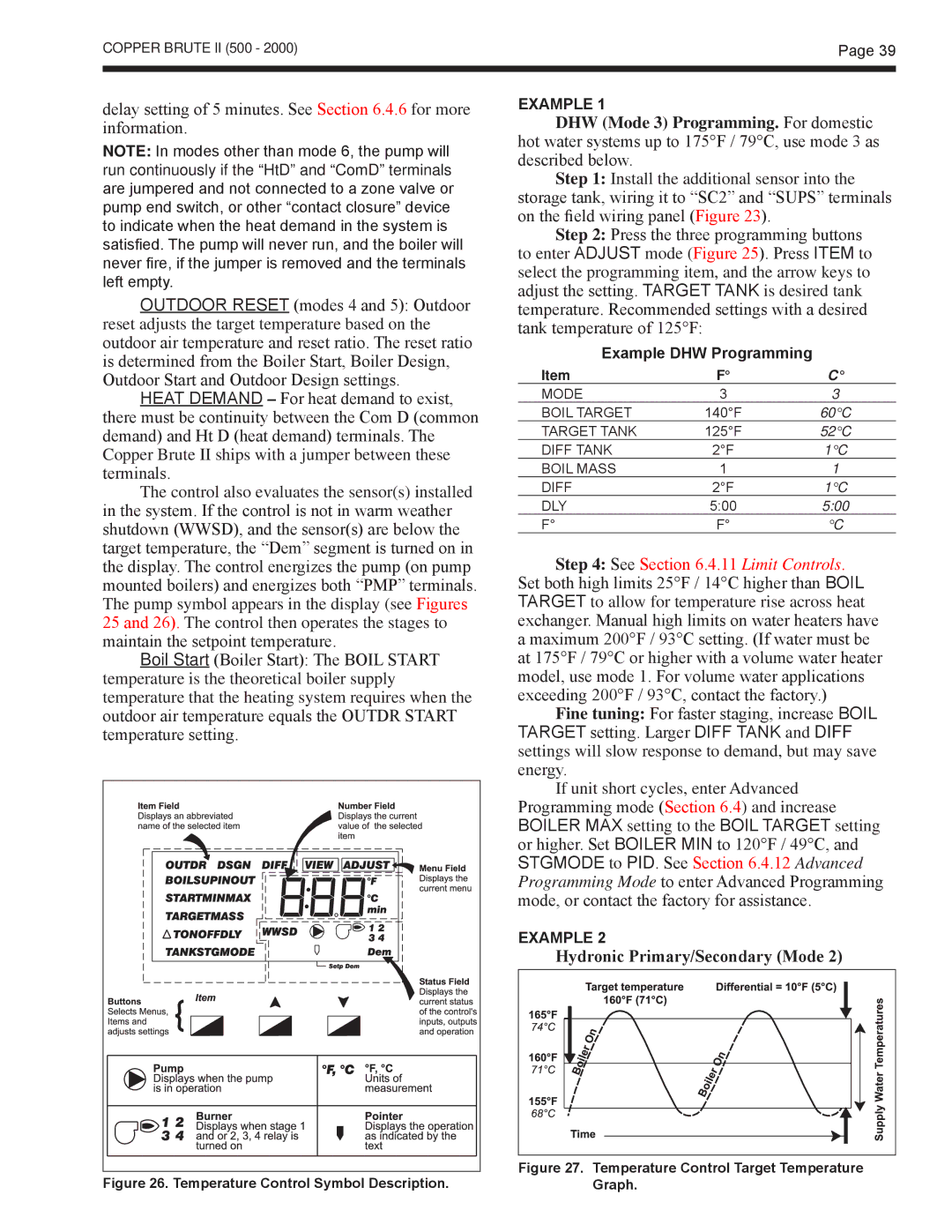
The control also evaluates the sensor(s) installed in the system. If the control is not in warm weather shutdown (WWSD), and the sensor(s) are below the target temperature, the “Dem” segment is turned on in the display. The control energizes the pump (on pump mounted boilers) and energizes both “PMP” terminals. The pump symbol appears in the display (see Figures 25 and 26). The control then operates the stages to maintain the setpoint temperature.
Boil Start (Boiler Start): The BOIL START temperature is the theoretical boiler supply temperature that the heating system requires when the outdoor air temperature equals the OUTDR START temperature setting.
EXAMPLE 1
DHW (Mode 3) Programming. For domestic hot water systems up to 175°F / 79°C, use mode 3 as described below.
Step 1: Install the additional sensor into the
storage tank, wiring it to “SC2” and “SUPS” terminals on the field wiring panel (Figure 23).
Step 2: Press the three programming buttons to enter ADJUST mode (Figure 25). Press ITEM to select the programming item, and the arrow keys to adjust the setting. TARGET TANK is desired tank temperature. Recommended settings with a desired tank temperature of 125°F:
Example DHW Programming
Item | F° | C° |
MODE | 3 | 3 |
BOIL TARGET | 140°F | 60°C |
TARGET TANK | 125°F | 52°C |
DIFF TANK | 2°F | 1°C |
BOIL MASS | 1 | 1 |
DIFF | 2°F | 1°C |
DLY | 5:00 | 5:00 |
F° | F° | °C |
Step 4: See Section 6.4.11 Limit Controls. Set both high limits 25°F / 14°C higher than BOIL TARGET to allow for temperature rise across heat exchanger. Manual high limits on water heaters have a maximum 200°F / 93°C setting. (If water must be at 175°F / 79°C or higher with a volume water heater model, use mode 1. For volume water applications exceeding 200°F / 93°C, contact the factory.)
Fine tuning: For faster staging, increase BOIL TARGET setting. Larger DIFF TANK and DIFF settings will slow response to demand, but may save energy.
If unit short cycles, enter Advanced
Programming mode (Section 6.4) and increase BOILER MAX setting to the BOIL TARGET setting or higher. Set BOILER MIN to 120°F / 49°C, and STGMODE to PID. See Section 6.4.12 Advanced Programming Mode to enter Advanced Programming mode, or contact the factory for assistance.
EXAMPLE 2
Hydronic Primary/Secondary (Mode 2)
| Figure 27. Temperature Control Target Temperature | |
Figure 26. Temperature Control Symbol Description. | ||
Graph. |